
Shock absorbing tube

a technology of shock absorption tube and shock absorption tube, which is applied in the direction of shafts, shafts, mechanical equipment, etc., can solve the problems of deterioration of the impact energy absorption effect, complicated production process, and complicated structur

Inactive Publication Date: 2004-01-27
TORAY IND INC
View PDF7 Cites 17 Cited by
  • Summary
  • Abstract
  • Description
  • Claims
  • Application Information

AI Technical Summary

Benefits of technology

The technical effect of this patent is to provide a shock absorbing tube for automobiles that can reliably cause rupture in the tube with the breakage of the car body when the automobile undergoes a crash, thereby making it possible for the energy absorbing effect of the car body to be fully exerted. The shock absorbing tube is designed to have a cylindrical main body made of FRP, with metal joints that are joined to the ends of the main body. The orientation of the reinforcing fibers in the main body is determined based on the requirements of torsional strength and critical revolution. The layer structure is determined by appropriately combining the orientations of the reinforcing fibers to achieve the highest bending resonance frequency. The shock absorbing tube is designed to have a high impact energy absorbing effect and to meet the requirements of weight reduction in automobiles.

Problems solved by technology

This leads to deterioration in the impact energy absorbing effect.
However, in this conventional shock absorbing tube, it is necessary for the main body and the joints to be joined together through the intermediation of teeth of a complicated shape, a separating agent, etc., in order to secure the movement of the joints, resulting in a rather complicated structure.
Furthermore, a complicated production process is not avoided.
However, imparting such a high strength to the main body makes it difficult for the main body to be enlarged and broken by the compressive load.
Thus, it is quite difficult simultaneously to satisfy the above-mentioned fundamental requirements and the requirements regarding enlargement and rupture, which are contradictory to each other.
However, in such a construction, it is absolutely necessary for the outer diameter of the joints to be smaller than the inner diameter of the main body, resulting in a reduction in the degree of freedom in designing.
Thus, the conventional shock absorbing tubes can not be regarded as well balanced in terms of fundamental requirements regarding torsional strength, critical revolution, etc. and safety assurance for the passengers at the time of a collision.

Method used


Image

  • Shock absorbing tube
  • Shock absorbing tube
  • Shock absorbing tube

Examples


example 2

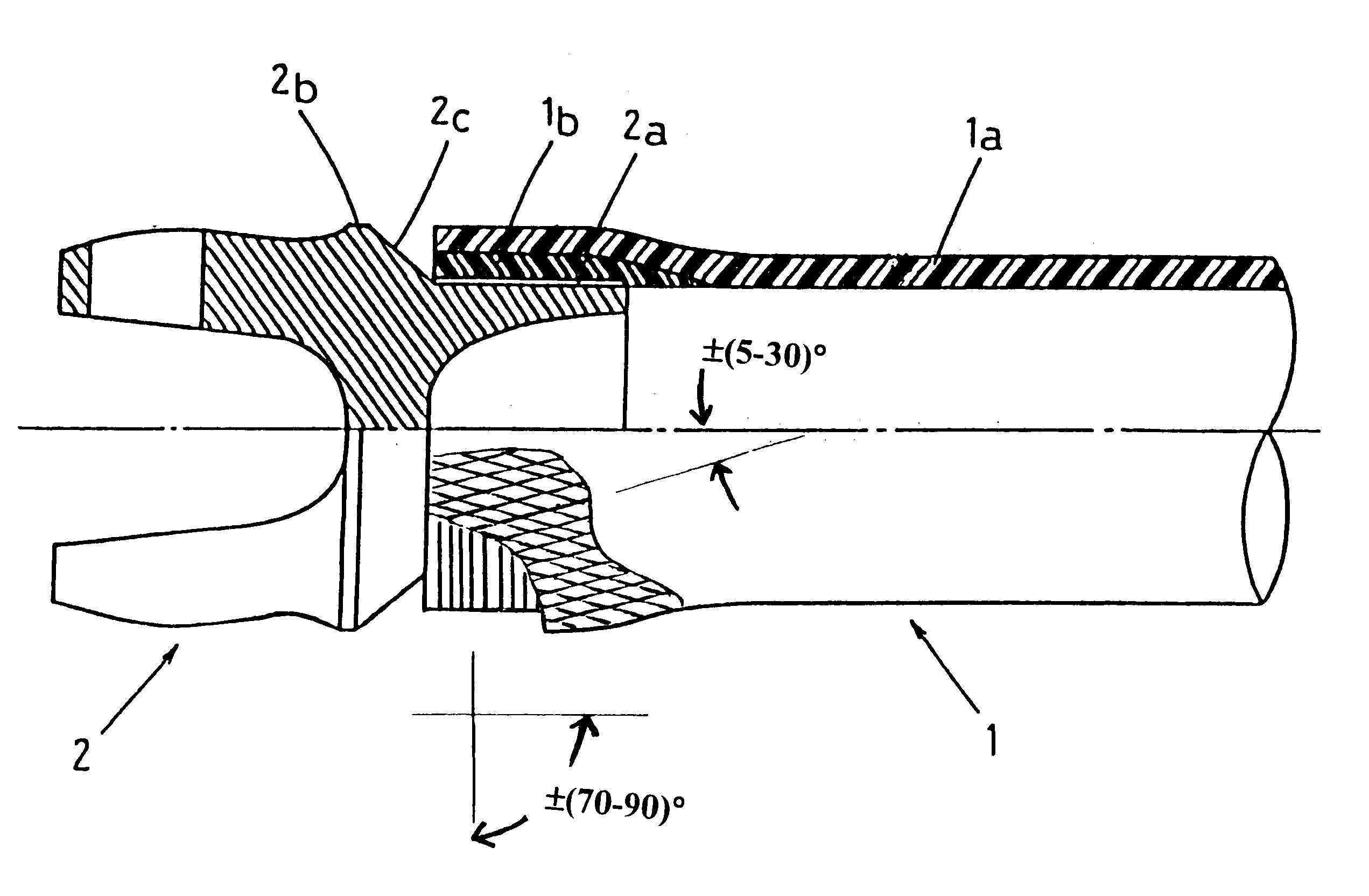
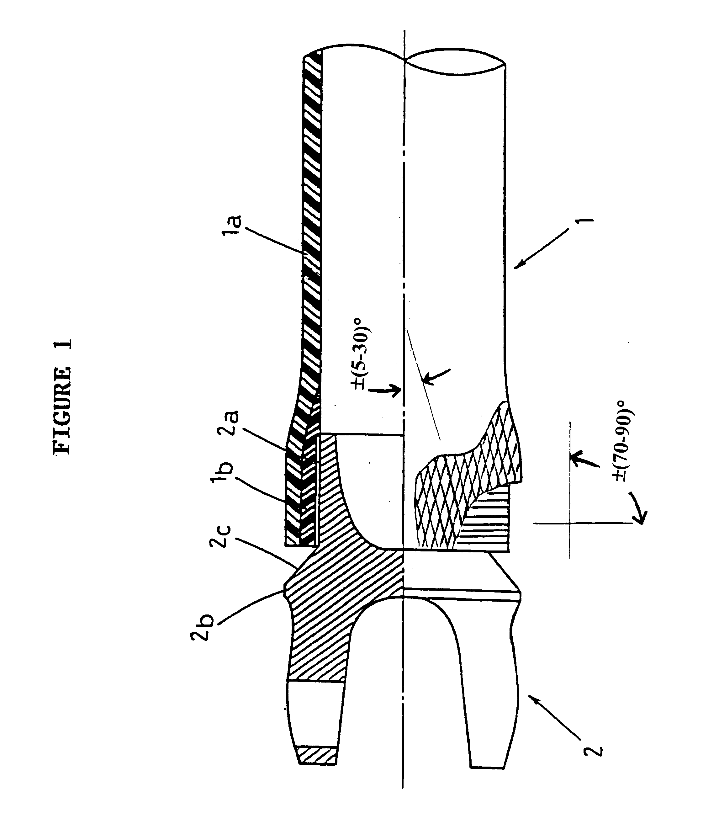
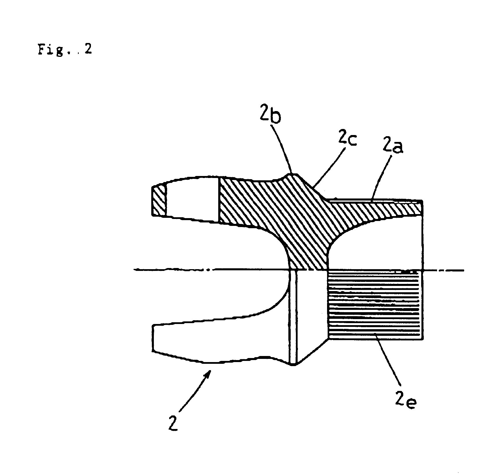
A shock absorbing tube as shown in FIG. 4 was obtained in the same manner as in Example 1 except that a joint was used the protrusion 2b of which had an outer diameter of 75 mm, which was the same as that of the end member 1b.

In a torsion test, the shock absorbing tube was found to have a torsional strength of 350 kgf.m and a critical revolution of 11,000 rpm, both of which proved satisfactory for a shock absorbing tube for automobiles.

Next, when an axial compressive load was applied, the main body and the end member were separated from each other at 11,000 kgf, and the rupture of the main body started. After the rupture, sequential breakage proceeded at a load of 3,500 kgf as shown in FIG. 5.

example 3

A shock absorbing tubes for collapsible handle system as shown in FIG. 4 was obtained in the same manner as in Example 1 except the following changes.

Firstly, the number of bungles of the end member was changed to four bundles (numbers of single fibers in total: 48,000) and four layers of fibers were wound on one end section of a length of 40 mm so as to be at an angle of .+-.85.degree. with respect to the axial direction to thereby form an end member having a thickness of 1.5 mm. After this, the procedure moved to the other end to form a similar end member on the other end section, and then two layers were wound over the entire length of the mandrel at an angle of .+-.22.5.degree. with respect to the axial direction to thereby form a main body having a thickness of 1.0 mm. Further, one layer was hooped over the entire length of the mandrel at an angle of -85.degree. with respect to the axial direction.

The shock absorbing tube had an end-portion outer diameter of 40 mm, a main body ...

example 4

A similar shock absorbing tubes to that of Example 3 was obtained in the same manner as in Example 3 except changing the end member to that made of aluminum.

When an axial compressive load was applied selectively to the end member of the shock absorbing tube, the main body and the end member were separated from each other at 300 kgf to thereby start rupture of the main body. After the rupture, sequential rupture as shown in FIG. 10 took place at a load of 150 kgf.

The shock absorbing tube of this invention is equipped with a compressive load transmitting section which concentrates a compressive load acting in the axial direction of the joint on the interface between the main body and the end member to thereby separate the main body and the end member from each other. Thus, as shown with reference to the embodiments, it is possible, at the time of collision, to allow the rupture of the shock absorbing tube to proceed reliably with the rupture of the car body while satisfying the fundam...


PUM


Abstract

A shock absorbing tube comprising a cylindrical main body made of fiber-reinforced plastic and an end member formed internally at an end of the main body, the main body and the end member are capable of separating from each other at an interface therebetween upon the application of a predetermined maximum axial force (Fm) and is capable of moving axially by sequentially enlarging the main body at a predetermined successive axial force (Fs), wherein the main body comprises reinforcing fibers helically wound at an angle of ±5-30° with respect to the axial direction of the main body and the end member is made of a metal or comprises reinforcing fibers hoop wound at an angle of ±70~90° with respect to the axial direction of the end member. The shock absorbing tube is useful for human safety, in particular, for use of propeller shaft and collapsible handle of automobiles.

Description

This invention relates to a shock absorbing tube such as for drive shaft of automobiles and the like.TECHNICAL BACKGROUNDNowadays, there is a great demand for safety design and weight reduction in automobiles from the viewpoint of passenger's safety and fuel economy improvement, etc. As a means for achieving this, use of shock absorbing tube such as for propeller shaft and collapsible parts of steering system formed of FRP (fiber-reinforced plastics) are being considered, and some of them have already been put into practical use. Such an FRP shock absorbing tube has a cylindrical main body that is made of FRP, and metal joints that are joined to the ends of this main body.An automobile propeller shaft, which serves to transmit torque generated in the engine to driving wheels, is required to have a torsional strength of approximately 100-400 kgf.m. Further, it is also required to have a high critical revolution of approximately 5,000 to 15,000 rpm in order that resonance may be avoid...

Claims


Application Information

Patent Timeline
Patent Type & Authority Patents(United States)
IPC IPC(8): F16C3/02
CPCF16C3/026F16C2326/06
Inventor KIMOTO, YUKITANEKAWANOMOTO, YASUYUKIOCHI, YUTAKANAKAMURA, MINORU
Owner TORAY IND INC
Learn More