Multiway valve for switching a flow of fluid under pressure with parallel disposition of valve bores, and valve assembly kit

Inactive Publication Date: 2004-02-10
AB REXROTH MECMAN
View PDF13 Cites 38 Cited by
  • Summary
  • Abstract
  • Description
  • Claims
  • Application Information

AI Technical Summary

Benefits of technology

According to another feature of the present invention, at least the valve housing may be made of plastics through an injection molding process such that the bores are simultaneously formed. In thi

Problems solved by technology

This or similar types of multiway valves with valve spool arrangement suffer shortcomings as the valve bore extends along the valve housing to accommodate the valve spools in coaxial dispositi

Method used


Image

  • Multiway valve for switching a flow of fluid under pressure with parallel disposition of valve bores, and valve assembly kit
  • Multiway valve for switching a flow of fluid under pressure with parallel disposition of valve bores, and valve assembly kit
  • Multiway valve for switching a flow of fluid under pressure with parallel disposition of valve bores, and valve assembly kit

Examples


first embodiment

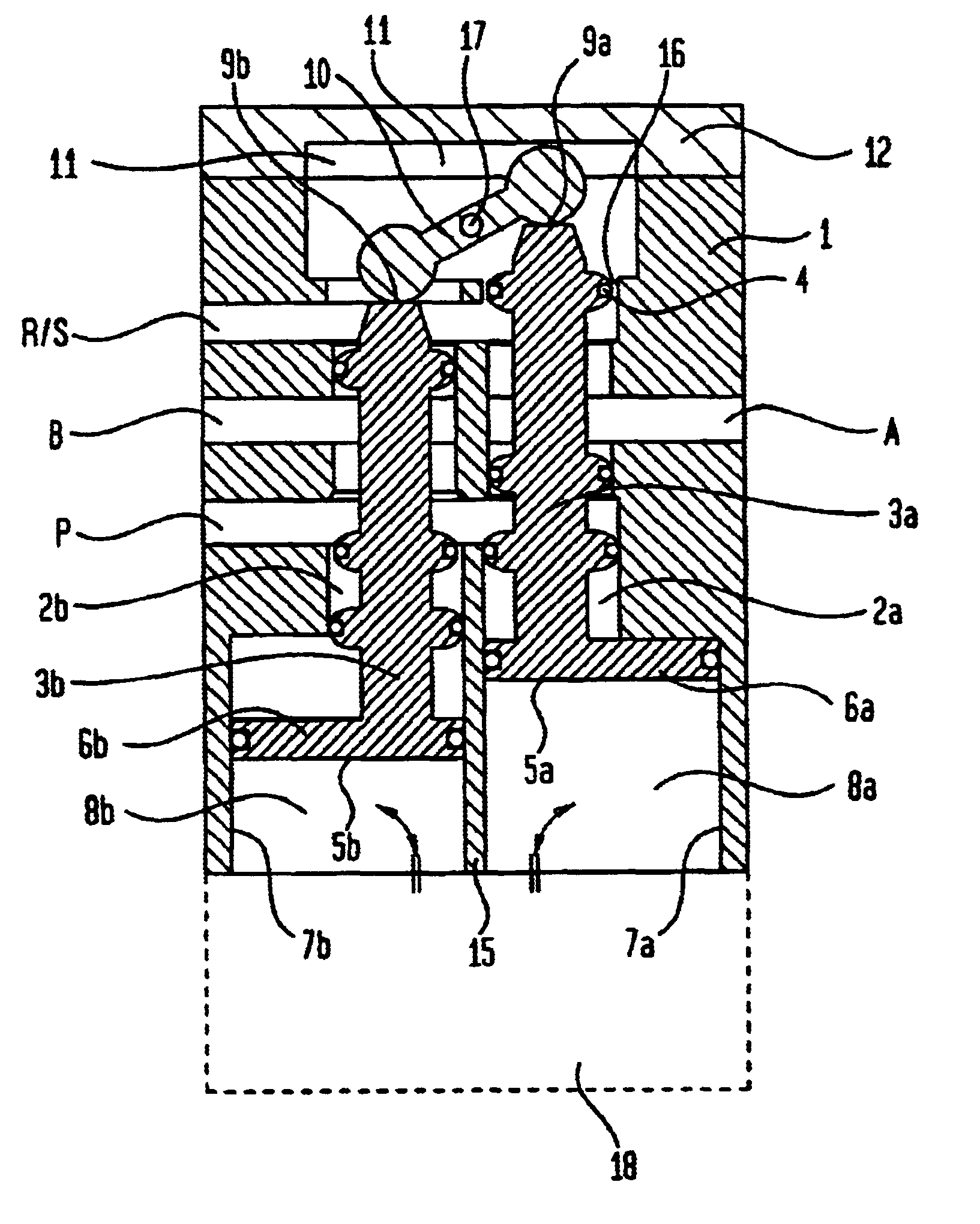
Turning now to the drawing, and in particular to FIG. 1, there is shown a longitudinal section of a multiway valve according to the present invention for producing a 5 / 2 way valve function. The multiway valve, here, by way of example, a pneumatic multiway valve, includes a valve housing 1 having several outer fluid ports P, A, B, R / S. Formed interiorly of the valve housing 1 at substantially a same level are two valve bores 2a, 2b arranged in parallel side-by-side disposition and separated by a partition wall 15 of the valve housing 1. The bore 2a accommodates a valve spool 3a for movement in a longitudinal direction, and the bore 2b accommodates a valve spool 3b for movement in a longitudinal direction. The valve spools 3a, 3b have each areas of greater diameter and areas of smaller diameter, whereby the areas of greater diameter have anchoring grooves 16 for receiving sealing rings 4 to thereby seal the spools 3a, 3b against the valve housing 1. As the spools 3a, 3b move in longit...

second embodiment

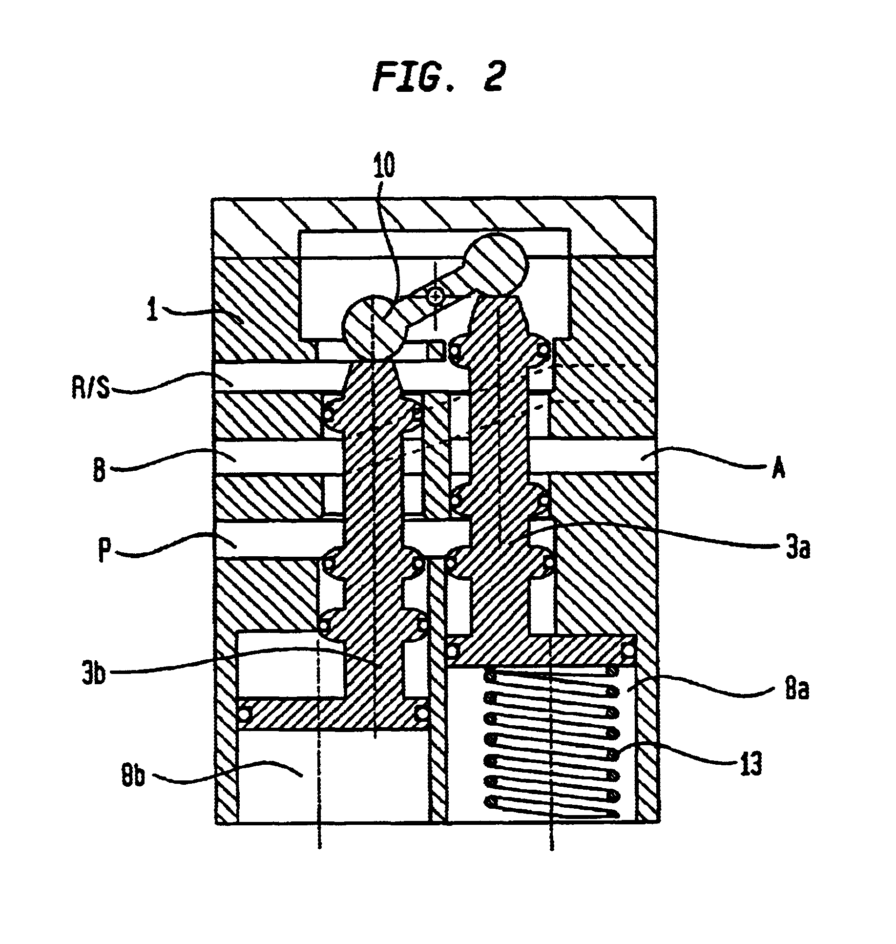
Referring now to FIG. 2, there is shown a longitudinal section of second embodiment of a multiway valve according to the present invention for producing a 5 / 2 way valve function. Parts corresponding with those in FIG. 1 are denoted by identical reference numerals and not explained again. In this embodiment, provision is made for the placement of a return spring 13 within the control chamber 8a. As a result, the displacement of both valve spools 3a, 3b in one switching direction is implemented through admission of a fluid under pressure into the control chamber 8b only. Restoring the other switching position is realized by the return spring, thereby establishing a monostable 5 / 2 way valve function.

third embodiment

FIG. 3 shows a longitudinal section of a multiway valve according to the present invention for producing two 3 / 2 way valve functions. Again, parts corresponding with those in FIG. 1 are denoted by identical reference numerals and not explained again. In this embodiment, provision is made for accommodation of two return springs 14a, 14b within the common space 11, to replace the mechanical coupler 10. The return springs 14a, 14b extend between the lid 12 and a confronting wall section of the uppermost anchoring groove 16 of the valve spools 3a, 3b. In the description, the term "uppermost" will denote a direction toward those portions of the valve assembly which appear on top of FIG. 3.

In contrast to the multiway valve, shown in FIGS. 1 and 2, in which the valve spools 3a, 3b are linked to one another and thus cannot move independently from one another, the multiway valve of FIG. 3 allows a separate switching of the valve spools 3a, 3b as a consequence of the absence of any linkage th...


PUM


Abstract

A multiway valve for controlling a flow of fluid under pressure, includes a valve housing having fluid ports and a plurality of bores in side-by-side parallel disposition substantially at a same level. Each bore is configured for accommodation of a valve spools which are sealed in the bores against the valve housing. The spools have opposite first and second end faces, and include portions of greater diameter and portions of smaller diameter. Acting on the first end face of the spools is an actuation unit for moving the spools in a longitudinal direction to thereby direct a flow of fluid under pressure between the ports, whereas a mechanical coupling mechanism, which is secured to the valve housing, interacts with the second end faces of the spools.

Description

CROSS-REFERENCES TO RELATED APPLICATIONSThis application claims the priority of German Patent Application Serial No. 101 09 206.7, filed Feb. 26, 2001, the subject matter of which is incorporated herein by reference.BACKGROUND OF THE INVENTIONThe present invention relates, in general, to directional control valves for directing a flow of fluid under pressure to a point of application, and more particularly to a pneumatic multiway valve of a type having a valve housing provided with outer ports for controlling the fluid flow between the ports.German Pat. No. 44 00 760 A1 discloses a multiway valve which has a valve housing formed interiorly with a valve bore which extends axially through the valve housing and includes grooves for receiving sealing rings in axially spaced-apart disposition. Mounted in the valve bore is a valve spool arrangement which is moveable in a longitudinal direction by a pilot piston, when the pilot piston is acted upon by a control pressure, so as to regulate ...

Claims


Application Information

Patent Timeline
IPC IPC(8): F15B13/04F15B13/042F15B13/00F16K31/122F16K11/07F16K11/10F16K11/22F16K11/065
CPCF15B13/0402F15B13/042F16K11/07F16K11/22F16K31/122F15B2013/006Y10T137/87209Y10T137/87225Y10T137/87764
Inventor LIESENHOFF, THOMAS
Owner AB REXROTH MECMAN
Why Eureka
Try Eureka