
Image processing method, image processing apparatus and recording medium

Inactive Publication Date: 2004-02-17
CANON KK
View PDF15 Cites 167 Cited by
  • Summary
  • Abstract
  • Description
  • Claims
  • Application Information

AI Technical Summary

Problems solved by technology

In not a few cases, however, inputs of the photographic images are accompanied by causes for image degradation such as color fog for reasons which will be described below.
Though the rays are processed with an infrared cut filter or the like needless to say, the processing is not always complete and colors may be unbalanced on the image.
Though man observes an object while correcting (adapting himself to) a difference of light source colors as known well, a camera records the difference of light source colors on a film with no correction and may provide a result which looks like color fog even when the camera accurately measures and reproduces the colors.
However, it is impossible in certain cases to obtain sufficiently satisfactory results even when images are corrected by using the standard concentration points which are set as described above.
In contrast, the camera is under a direct influence from the light sources and reproduces colors with a high calorimetric fidelity, thereby posing a problem that it cannot reproduce colors which are preferred by man.
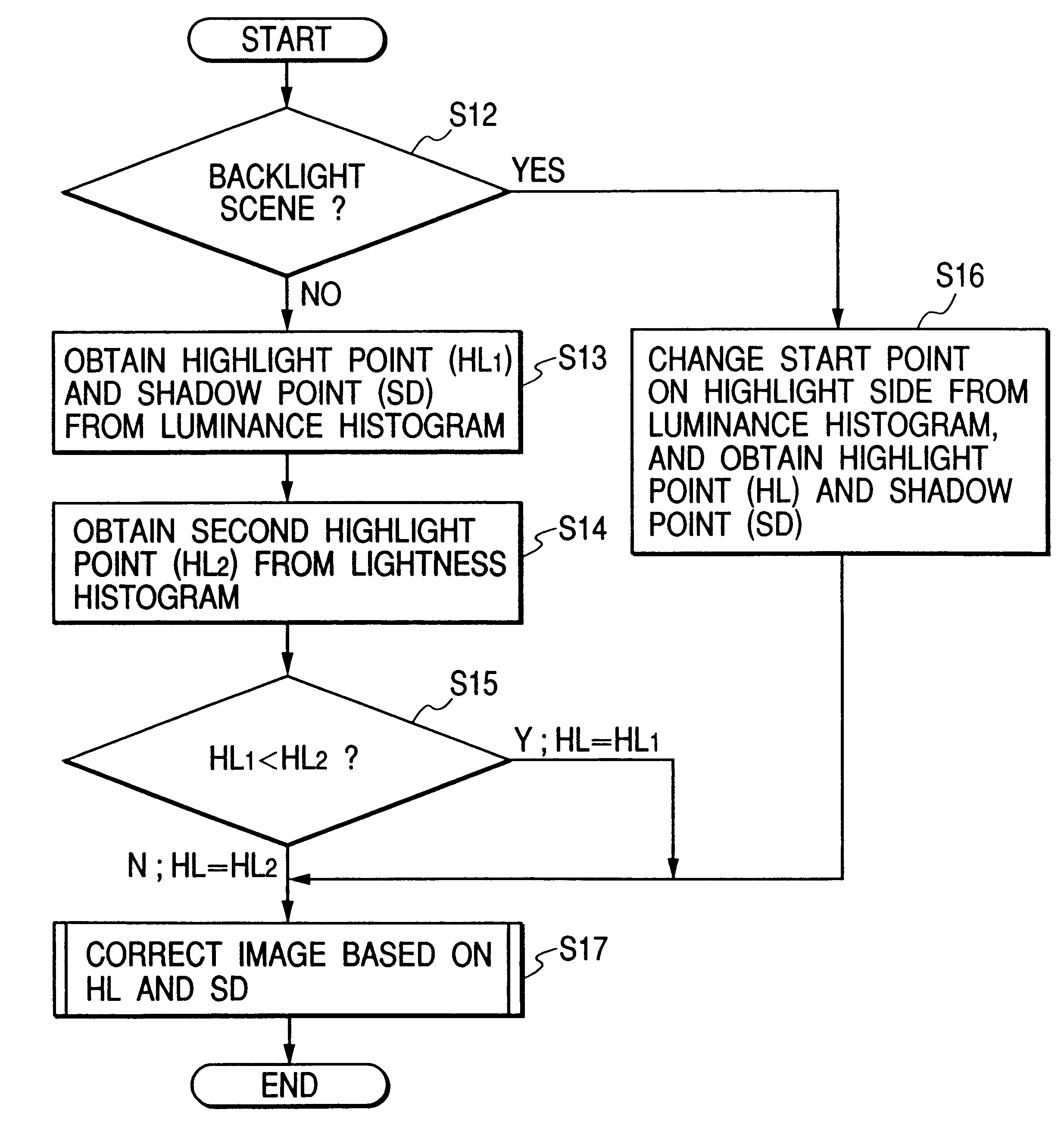
In case of a photograph a most portion of which is occupied by a blue sky, however, it is not always possible to set an optimum highlight point from the conventional histogram which is prepared from the luminance signals having the weights since the B signal has a low weight.
When a person or the like is photographed in a backlight condition, a main object is rather underexposed, thereby making it impossible to obtain favorable gradations.
When a highlight point which is set at 99%, for example, from an accumulated frequency histogram shown in FIG. 10, for example, as described with reference to the related art, the high lightpoint is fixed nearly to a maximum luminance and correction with this histogram is almost ineffective.
Furthermore, digital input images may not be exposed adequately for a reason which will be described below.
In photographing with an ordinary camera which is not set for adequate exposure, for example, an image may be too bright or too dark due to overexposure or underexposure, thereby making details of an object illegible.
Exposure correction which is made by visual confirmation may result in an overexposure condition due to the invisible infrared rays picked up by the CCD device even if exposure is adequate for the visible rays.
Though the rays are processed with an infrared cut filter or the like, the processing is not always complete and may allow a condition such as that described above.
Moreover, there are cases where adequate exposure provides conditions which look like underexposure.
Accordingly, an error may be made at a stage to detect a white location when the pixel is used for preparation of a luminance histogram.
Therefore, exposure correction of the backlight scene similar to that in the first embodiment may converts too many pixels of the original image into white, thereby lowering a quality of an output image.

Method used


Image

  • Image processing method, image processing apparatus and recording medium
  • Image processing method, image processing apparatus and recording medium
  • Image processing method, image processing apparatus and recording medium

Examples


first embodiment

When a person or the like is photographed in a backlight condition, a main object is rather underexpose, thereby making it impossible to obtain favorable gradations. When a highlight point is set for such an image as in the first embodiment, it is fixed nearly to a highest luminance and correction on the basis of this highlight point is almost ineffective.

In the embodiment 6-2, a value of a highlight point to be converted is modified so as to adequately correct the image the most portion of which is occupied by the blue sky or the image of the person photographed in the backlight condition. A method adopted for the embodiment 6-2 not only creates a luminance histogram but also calculates an average value M of R, G and B signals by an equation M=(R+G+B) / 3, creates a histogram (hereinafter referred to as an average signal value histogram) on the basis of M and determines a highlight point M.sub.HL from this histogram. Thereafter, the image processing system compares a highlight point ...

embodiment 6-2

The embodiment 6-2 which selectively uses the LUTs shown in FIG. 28 and FIG. 30 depending on images is capable of preventing a relatively dark image such as one photographed at night from being unnaturally bright by image correction. Furthermore, images can be corrected optimally while preventing the color skip also by the method which compares the highlight point on the luminance histogram with that of the average signal value histogram for effective reproduction of the image which is mostly occupied by the blue sky and the image photographed in the backlight condition.

The formats of the LUTs used in the embodiment 6-2 which are typically represented by those shown in FIG. 28 and FIG. 30 are only exemplary, and various values may apply to LUTS depending on the kinds of images and degrees of correction.

Other Embodiments

Though the color fog correction is carried out first and then the underexposure or overexposure correction is performed to adjust contrast in the embodiments describe...


PUM


Abstract

An image processing method, an image processing system and a recording medium capable of reproducing images in colors which are close to those memorized by man including a process to create a histogram of an original image, a process to adequately locate a highlight point on the histogram by comparing peaks of the histogram and setting image processing conditions dependently on a shape of a selected peak.

Description

1. Field of the InventionThe present invention relates to an image processing method to determine a highlight point, an image processing apparatus and a recording medium.2. Related Background ArtIn these years where personal computers had higher speeds, memory capacities were enlarged rapidly, and digital cameras, film scanners or the like widely prevail, there were increasing occasions to process images of photographic tones as digital data with personal computers. In not a few cases, however, inputs of the photographic images are accompanied by causes for image degradation such as color fog for reasons which will be described below.For example, when a digital camera is taken as an example, rays which have wavelengths insensible by a man's eye such as infrared rays may be taken into an image photographed by a CCD camera. Though the rays are processed with an infrared cut filter or the like needless to say, the processing is not always complete and colors may be unbalanced on the im...

Claims


Application Information

Patent Timeline
IPC IPC(8): G06T5/40G06T5/00H04N1/60H04N1/407
CPCG06T5/009G06T5/40H04N1/4074H04N1/6077G06T5/92
Inventor YAMAZOE, MANABUYANO, KENTAROSUWA, TETSUYATSUCHIYA, OKINORI
Owner CANON KK
Learn More