Evaporated fuel treatment apparatus

a technology of evaporation fuel and treatment apparatus, which is applied in the direction of combustion air/fuel air treatment, machine/engine, separation process, etc., can solve the problems of increasing manufacturing cost, complex structure, and correspondingly complicated structure, and achieve satisfactory adsorption/desorption performance, reduce manufacturing cost, and reduce the effect of refilling tim

Inactive Publication Date: 2004-02-24
HONDA MOTOR CO LTD
View PDF12 Cites 55 Cited by
  • Summary
  • Abstract
  • Description
  • Claims
  • Application Information

AI Technical Summary

Benefits of technology

The present invention has been made to solve the foregoing problems, and it is an object of the invention to provide an evaporated fuel treatment apparatus which is capable of reducing a refilling time, ensuring satisfactory adsorption / desorption performance for an evaporated fuel, and reducing the manufacturing cost through simplification of the structure.
According to the evaporated fuel treatment apparatus, an evaporated fuel generated in the fuel tank is introduced into the main chamber, and then introduced into the sub-chamber before it is emitted to the atmosphere. In this event, the evaporated fuel is emitted to the atmosphere after fuel components contained therein are adsorbed by the main adsorbent and sub-adsorbent. In this manner, the evaporated fuel generated in the fuel tank flows along the same flow passage either during refilling or during a normal operation, unlike before, so that the same length can be ensured for the flow passage during refilling as that during the normal operation. Since the air-flow resistance of the sub-chamber including the sub-adsorbent is set smaller than that of the main chamber including the main adsorbent, it is possible to suppress a rise in the overall air-flow resistance of the main chamber and sub-chamber during refilling. Also, the main fuel adsorbent in the main chamber, having a larger air-flow resistance adsorbs, a majority of fuel components in the evaporated fuel, while the sub-adsorbent in the sub-chamber complementally adsorbs the remaining fuel components, thereby making it possible to effectively adsorb the fuel components in the evaporated fuel, and maintain satisfactory adsorption performance. This can lead to a reduction in refilling time during refilling, and to the satisfactory adsorption performance ensured for the evaporated fuel. In addition, since the present invention eliminates an electromagnetic valve, a discharge passage and the like for refilling, which have been conventionally required, the structure can be correspondingly simplified to reduce the manufacturing cost.
According to this preferred embodiment of the evaporated fuel treatment apparatus, the sub-adsorbent can be relatively easily manufactured.
According to this preferred embodiment of the evaporated fuel treatment apparatus, the sub-adsorbent surpassing in the strength can be relatively easily manufactured in an integral form.
According to this preferred embodiment of the evaporated fuel treatment apparatus, the two portions of the casing are arranged such that they are spaced apart from each other, so that larger contact areas can be ensured for the two portions of the casing in contact with external air, thereby making it possible to effectively cool or heat the adsorbents within the casing through heat exchanging with the external air. As a result, the adsorption / desorption performance can be improved for the evaporated fuel.

Problems solved by technology

The conventional evaporated fuel treatment apparatus requires the discharge control electromagnetic valve, fuel supply discharge passage, switch and the like provided for reducing the refilling time, thereby resulting in a correspondingly complicated structure and an increase in the manufacturing cost.
Also, the discharge control valve is susceptible to a leak of evaporated fuel.
This may fail to provide satisfactory adsorption / desorption performance for the evaporated fuel by the active carbons.

Method used


Image

  • Evaporated fuel treatment apparatus
  • Evaporated fuel treatment apparatus
  • Evaporated fuel treatment apparatus

Examples


Embodiment Construction

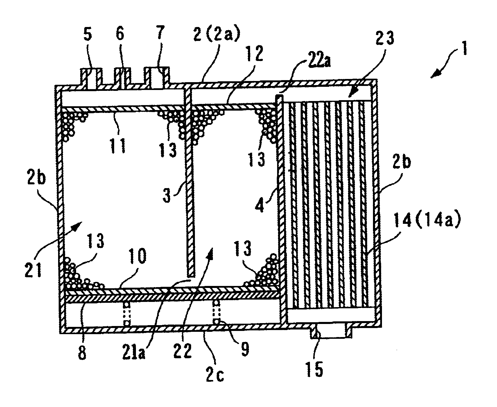
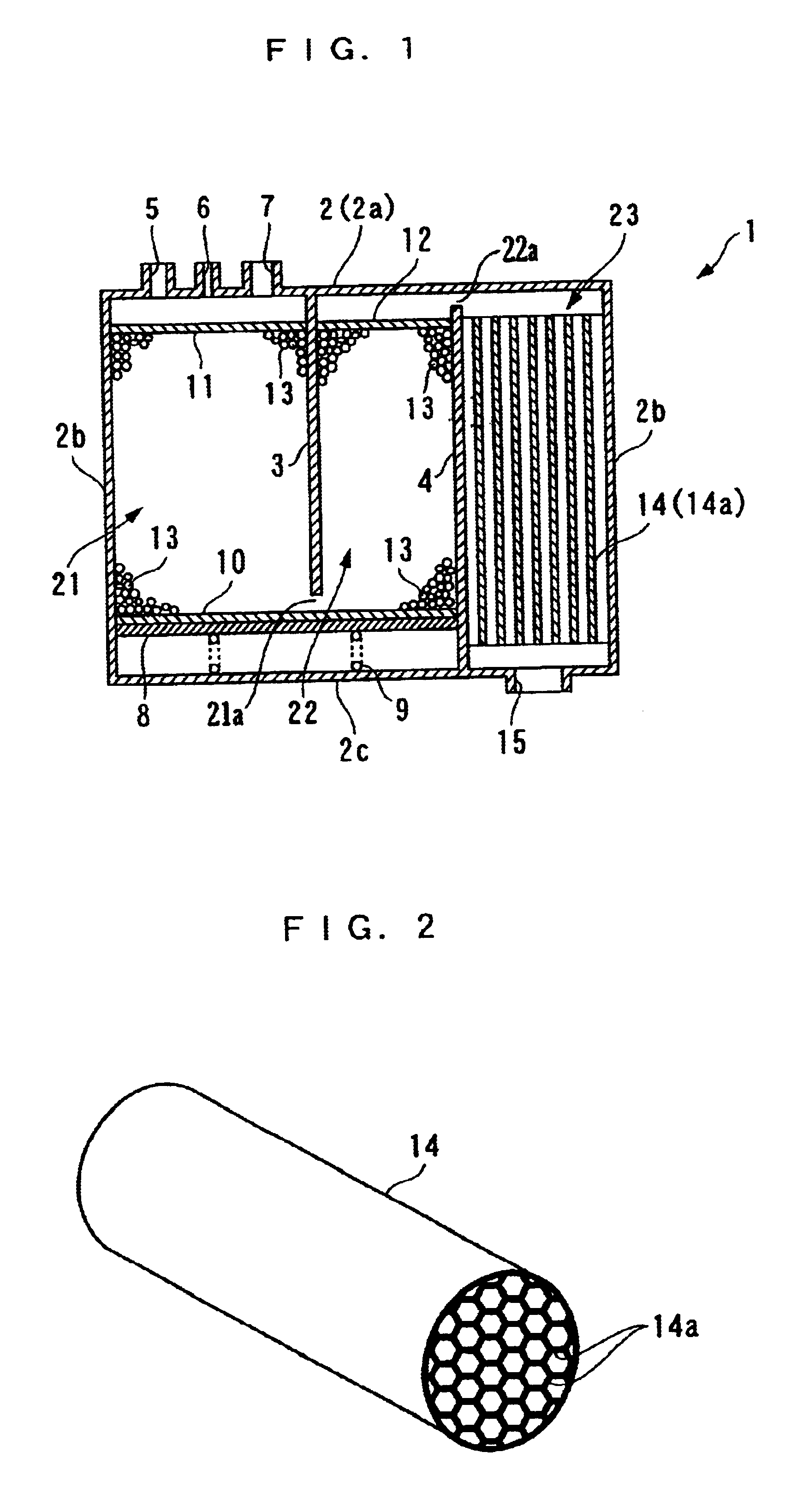
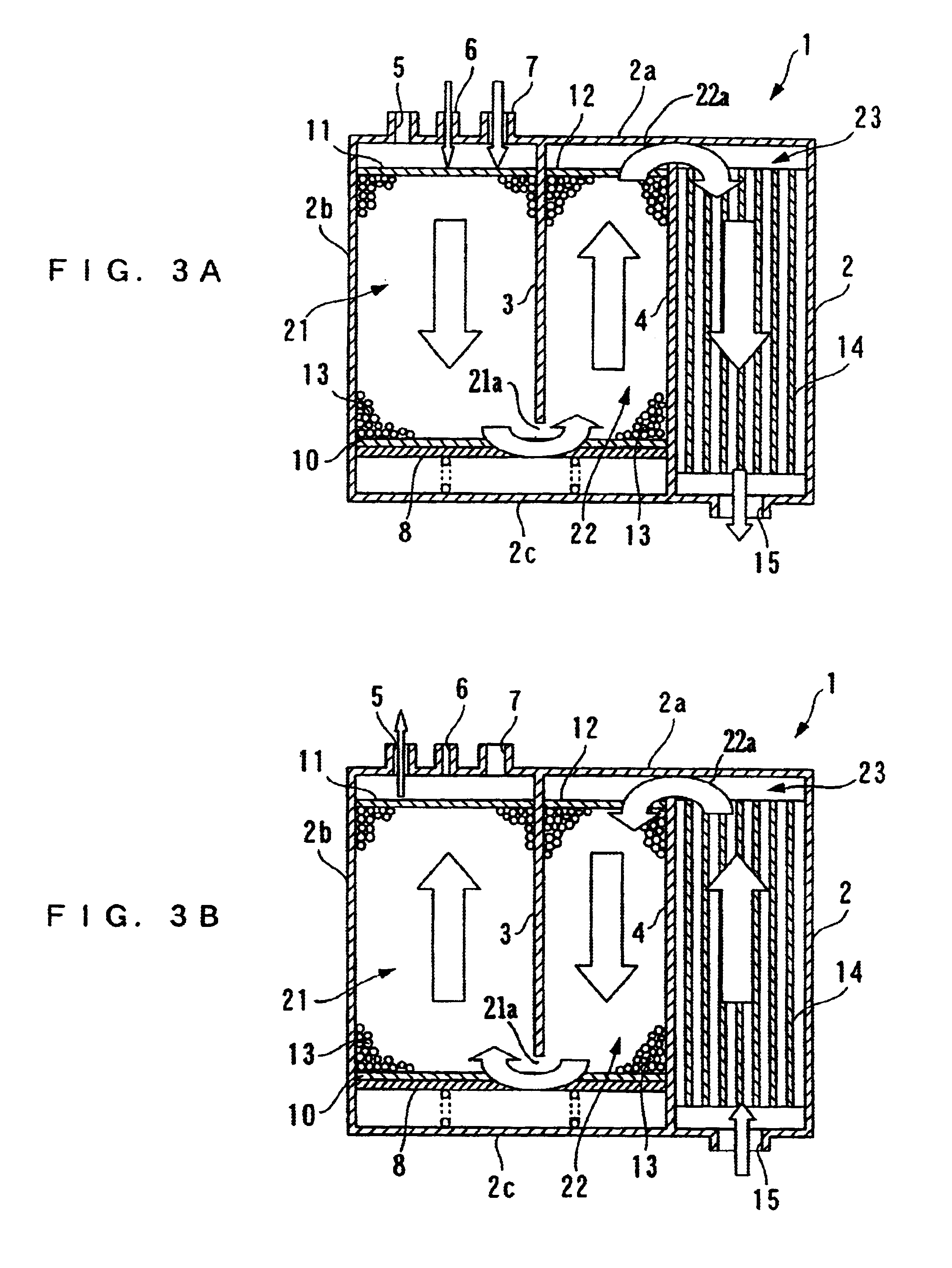
In the following, one embodiment of the present invention will be described in detail with reference to the accompanying drawings. FIG. 1 generally illustrates the structure of an evaporated fuel treatment apparatus according to the embodiment. As illustrated, the evaporated fuel treatment apparatus (hereinafter called the "canister") 1 comprises a casing 2 formed of a top wall 2a, four side walls 2b and a bottom wall 2c; a first chamber 21 (main chamber), a second chamber 22 (main chamber), and a third chamber 23 (sub-chamber) defined by partitioning the casing 2 by two partition walls 3, 4; and the like.

The top wall 2a of the first chamber 21 is provided with a purge port 5, a charge port 6, and a fuel supply charge port 7. A purge passage, in communication with an intake pipe of an engine (either of them is not shown in the figure), is connected to the purge port 5. A purge control valve, not shown, is disposed midway in the purge passage. The opening of the purge control valve i...


PUM

PropertyMeasurementUnit
grain diameteraaaaaaaaaa
air-flow resistanceaaaaaaaaaa
air permeabilityaaaaaaaaaa

Abstract

An evaporated fuel treatment apparatus is provided for reducing a refilling time, ensuring satisfactory adsorption / desorption performance for an evaporated fuel, and reducing the manufacturing cost through a simplified structure. The evaporated fuel treatment apparatus comprises a casing having formed therein a first chamber in communication with the fuel tank, a second chamber in communication with the first chamber, and a third chamber in communication with the second chamber and the atmosphere. Active carbons are contained in the first chamber and second chamber for adsorbing fuel components in an evaporated fuel introduced from the fuel tank. An adsorbent is contained in the third sub-chamber for adsorbing fuel components in the evaporated fuel introduced from the second chamber. The adsorbent has an air-flow resistance which is set smaller than that of the active carbons.

Description

1. Field of the InventionThe present invention relates to an evaporated fuel treatment apparatus which temporarily adsorbs fuel components within an evaporated fuel to conveniently discharge the evaporated fuel to an intake passage in order to prevent the emission to the atmosphere of the evaporated fuel generated in a fuel tank of an internal combustion engine.2. Description of the Prior ArtConventionally, the evaporated fuel treatment apparatus of the type mentioned above is generally called a canister, and is known, for example, from Laid-open Japanese Patent Application No. Hei 7-332171. This canister comprises a box-shaped casing; three chambers, a first through a third chamber defined by partitioning the casing by partition walls; and active carbons filled in each chamber. The first and second chambers, and the second and third chambers communicate with each other. The first chamber is connected to an intake pipe through a purge passage, and is also connected to a fuel tank th...

Claims


Application Information

Patent Timeline
Patent Type & Authority Patents(United States)
IPC IPC(8): B01D53/04F02M25/08
CPCB01D53/0446F02M25/0854B01D53/0415B01D2253/102B01D2253/304B01D2253/3425B01D2257/702B01D2258/01B01D2259/40081B01D2259/40086B01D2259/4516B01D2259/4566
Inventor HARA, TAKESHIMIHARA, HIROAKI
Owner HONDA MOTOR CO LTD
Why Eureka
Try Eureka