Electronically regulated self-controlled ventilation unit

a self-regulated, electric technology, applied in ventilation systems, heating types, stoves or ranges, etc., can solve the problems of significant thermal losses of the premises, increased noise acoustic disadvantage, and higher noise generation

Inactive Publication Date: 2004-03-02
ALDES AERAULIQUE
View PDF7 Cites 27 Cited by
  • Summary
  • Abstract
  • Description
  • Claims
  • Application Information

AI Technical Summary

Benefits of technology

The invention relates to a ventilation unit comprising a fan driven electrically, mounted inside a casing into which there open several ducts connected with one or more rooms, orifices of determined cross section and a differential-pressure sensor measuring a pressure difference between two predetermined points, the measured differential-pressure value being transmitted to an analysis and control device which compares the differential-pressure value with a reference value and controls rotational speed of the fan, so as to keep the differential-pressure value constant and equal to the reference value, and to maintain ventilation flow rates at the orifices at a desired flow rate. This ventilation unit may regulate a differential pressure which results in control over the flow rates at the ends of the ducts which have known passage cross sections and sizes. It is thus possible to get away from the noise associated with the increase in pressure through drop of flow rate and to get away from the use of a very expensive special-purpose fan.
Thus, the invention makes it possible to replace mechanical members for regulating the flow rate with simple calibrated and carefully shaped orifices, thus considerably reducing the overall cost of controlling the flow rates.
This results in a consumption which is always suited to the ventilation requirements with a low noise level even at low flow rate, and a broad coverage of the possible configurations.

Problems solved by technology

However, ventilation in which the flow rates are not controlled may lead to significant thermal losses for the premises.
Although these fans tolerate a broad range of differential pressures, they do have the major acoustic disadvantage of generating a level of noise that increases with the increase in differential pressure.
Thus, for low flow rates, the noise generated is higher, and this often forces manufacturers to offer a wide range of drive solutions in order to suit the various configurations of flow rate and in order not to generate needless excess consumption.
These needs may be associated with an increase in the pollution or moisture due to human presence.

Method used


Image

  • Electronically regulated self-controlled ventilation unit
  • Electronically regulated self-controlled ventilation unit
  • Electronically regulated self-controlled ventilation unit

Examples


first embodiment

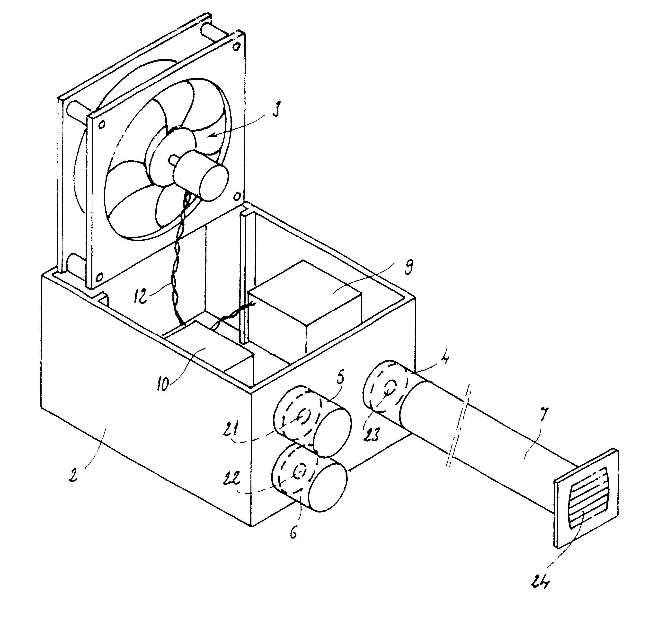
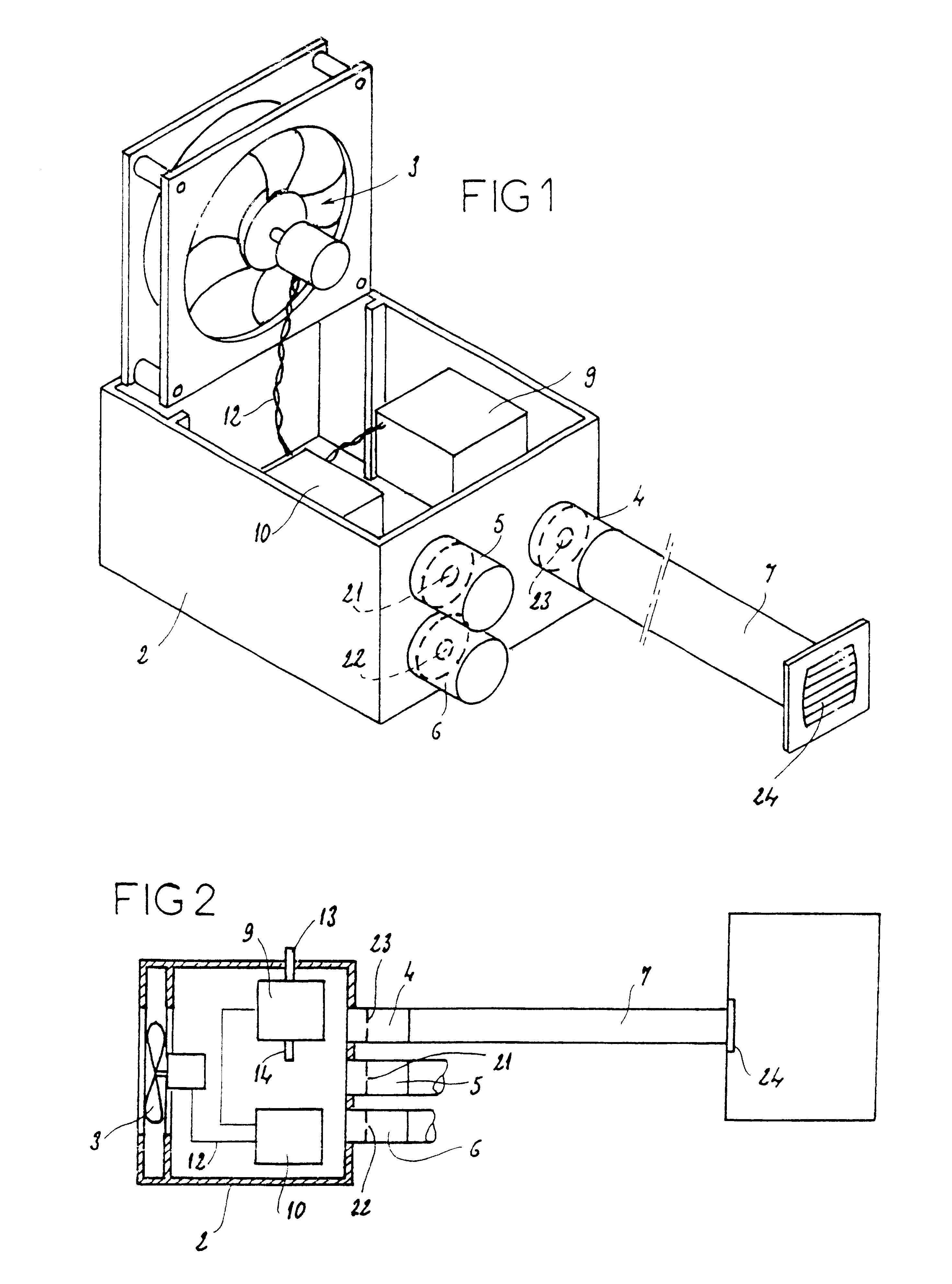
According to the invention depicted in FIG. 2, the differential-pressure sensor 9 measures the absolute pressure in the casing 2, that is, the pressure difference between the inside and the outside of the casing 2. To this end, a pressure tapping tube 13 opens outside of the casing and another pressure tapping tube 14 opens into the casing.

second embodiment

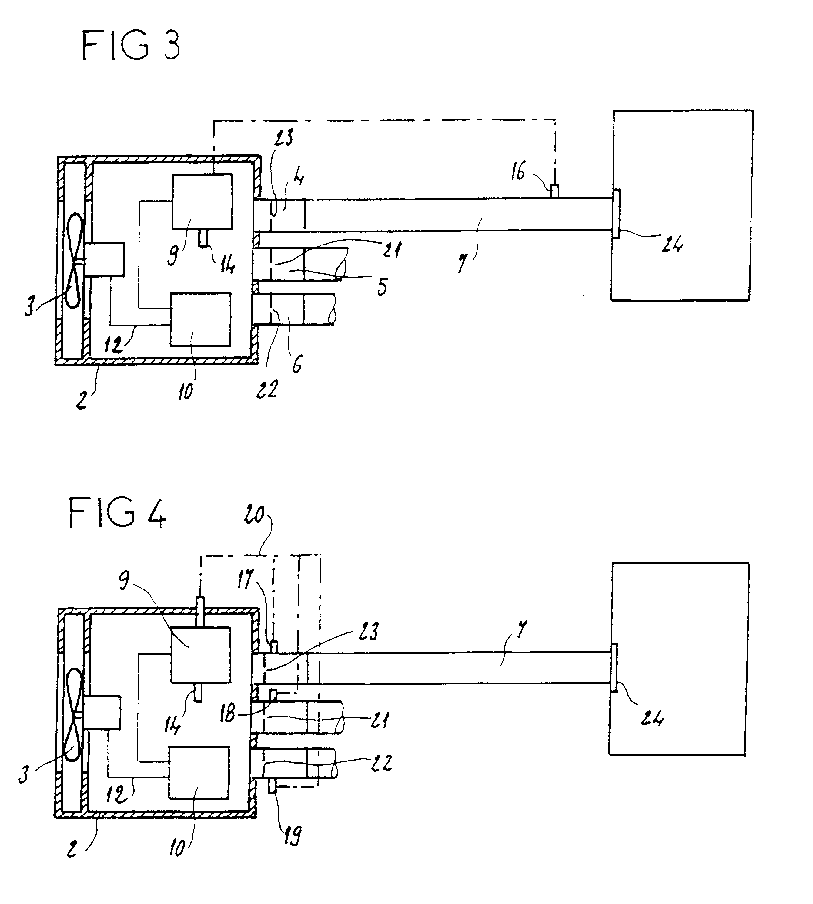
FIG. 3 depicts the invention in which the same elements are denoted by the same references as before. In this case, the differential-pressure sensor 9 measures the pressure difference between the inside of the casing 2 and a point 16 situated on the duct 7 beyond the orifice 23 with respect to the casing 2.

third embodiment

FIG. 4 depicts the invention in which the same elements are denoted by the same references as before. In this case, three tubes 17, 18 and 19 respectively, which meet as a common tube 20 connected to the pressure sensor 9, make it possible to determine the mean pressure in the ducts connected to the tappings 4, 5 and 6. The differential-pressure sensor 9 also takes the pressure inside the casing 2 via the tube 14. The sensor 9 measures the pressure difference between the mean pressure inside the ducts 7 and the pressure inside the casing 2, the orifices 21, 22 and 23 being arranged between the pressure tappings 4, 5, and 6.


PUM


Abstract

A ventilation unit is provided comprising an electronically driven ventilator, mounted inside a casing wherein emerge several ducts connected to one or several rooms. Said unit further comprises orifices with specific cross-section, and a differential-pressure sensor measuring the difference in pressure between two predetermined points, said value being transmitted to an analysis and control device, which compares the differential pressure value to a reference value and controls the ventilator, such that it accelerates or slows down it rotational speed, so as to maintain the differential pressure constant and equal to the reference value, to maintain the desired flow rate at said orifices.

Description

The present invention relates to an electronically regulated self-controlled ventilation unit operating in extraction or in blowing, allowing control over the flow rates, regardless of the ventilation uses, particularly variations in the number and nature of air intakes, continuous variations in flow rate, or variations in environment, particularly drops in electrical voltage supplied to the fan, variation in back pressure due to the wind, while at the same time optimizing the consumption and the acoustics, for any fan.BACKGROUND OF INVENTIONIn collective or individual homes, or in premises put to economical or industrial use, ventilation has to provide a minimum renewal of air, needed for health, air quality and building life. However, ventilation in which the flow rates are not controlled may lead to significant thermal losses for the premises. As a result, ventilation systems have to render the most stable possible air renewal flow rates while at the same time meeting constraints...

Claims


Application Information

Patent Timeline
Patent Type & Authority Patents(United States)
IPC IPC(8): F24F11/04F24F11/047F24F7/06F24F7/00F24F11/75
CPCF24F7/06F24F11/047F24F2007/002F24F2011/0042F24F2110/40F24F11/75F24F2140/10F24F11/77F24F11/0001
Inventor BOULANGER, XAVIERDAMIZET, PATRICK
Owner ALDES AERAULIQUE
Why Eureka
Try Eureka