Contactor

a contactor and contact technology, applied in the direction of air-break switches, high-tension/heavy-dress switches, electromagnetic relay details, etc., can solve the problems of small voltage rise speed of arc generated between contacts, difficult to swiftly break current, and inability to obtain excellent breaking performance. to achieve the effect of enhancing the breaking performance of an electric path

Inactive Publication Date: 2004-03-02
MATSUSHITA ELECTRIC WORKS LTD
View PDF10 Cites 137 Cited by
  • Summary
  • Abstract
  • Description
  • Claims
  • Application Information

AI Technical Summary

Benefits of technology

In the contact apparatus of such a structure, the arc generated between the fixing contact point and the movable contact point when the electric path is opened is moved sideways by the magnetic force of the permanent magnet and stretched. The arc length is increased and thus, the arc voltage rises. With this, the arc is swiftly extinguished, and the breaking performance of the electric path is enhanced.
In addition to the above, if an arc-extinguishing member made of insulative material capable of generating arc-extinguishing gas is provided in a region near the fixed contact point and the movable contact point, the arc is cooled by the arc-extinguishing gas. With this, the arc voltage further rises, the breaking performance of the electric path is further enhanced.

Problems solved by technology

In such a contact apparatus, it is difficult to swiftly break the current due to arc generated between contacts when an electric path is opened.
However, if the insulator for generating the arc-extinguishing gas is merely provided, a voltage rising speed of the arc generated between contacts is small, and there is a problem that excellent breaking performance can not always be obtained.

Method used


Image

  • Contactor
  • Contactor
  • Contactor

Examples


embodiment 1

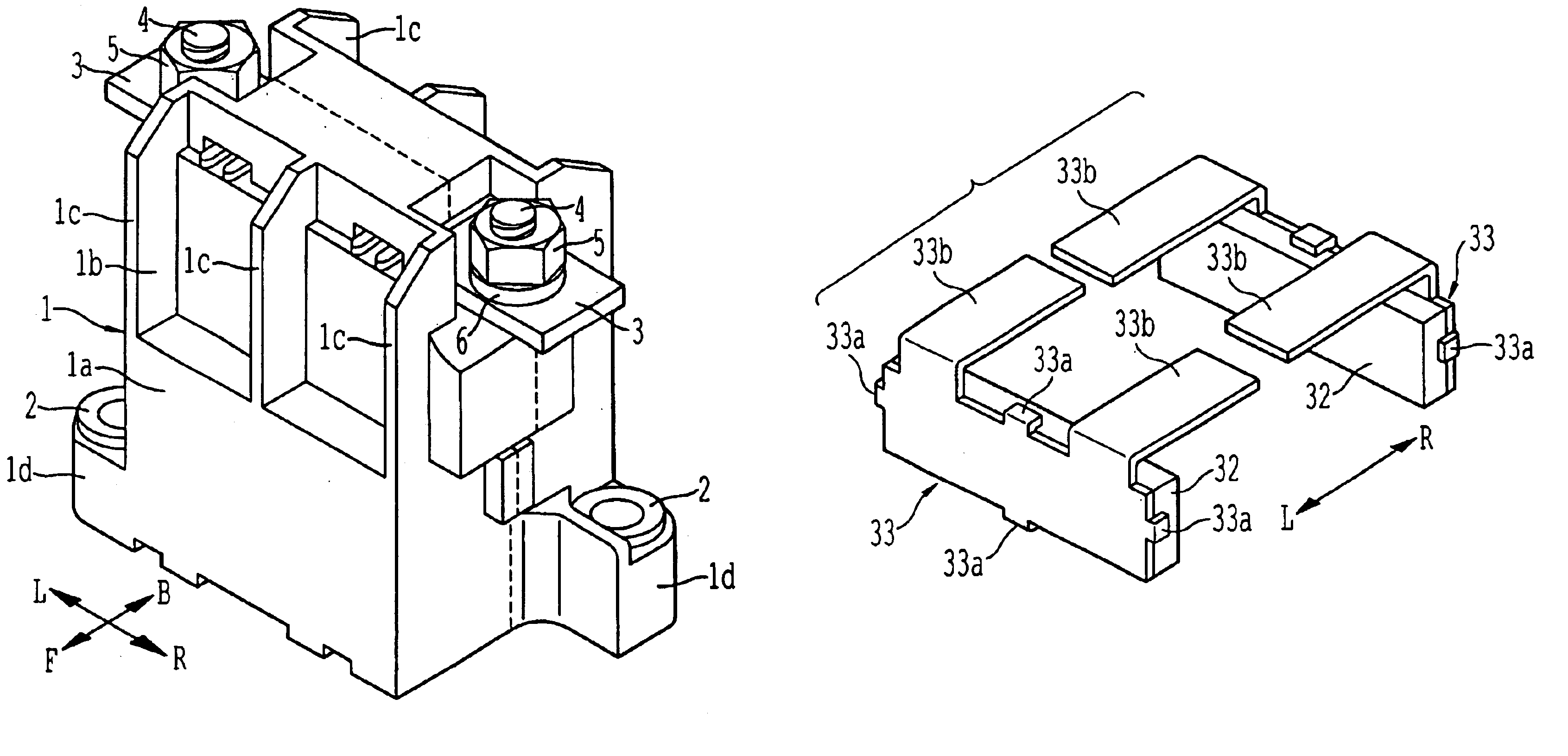
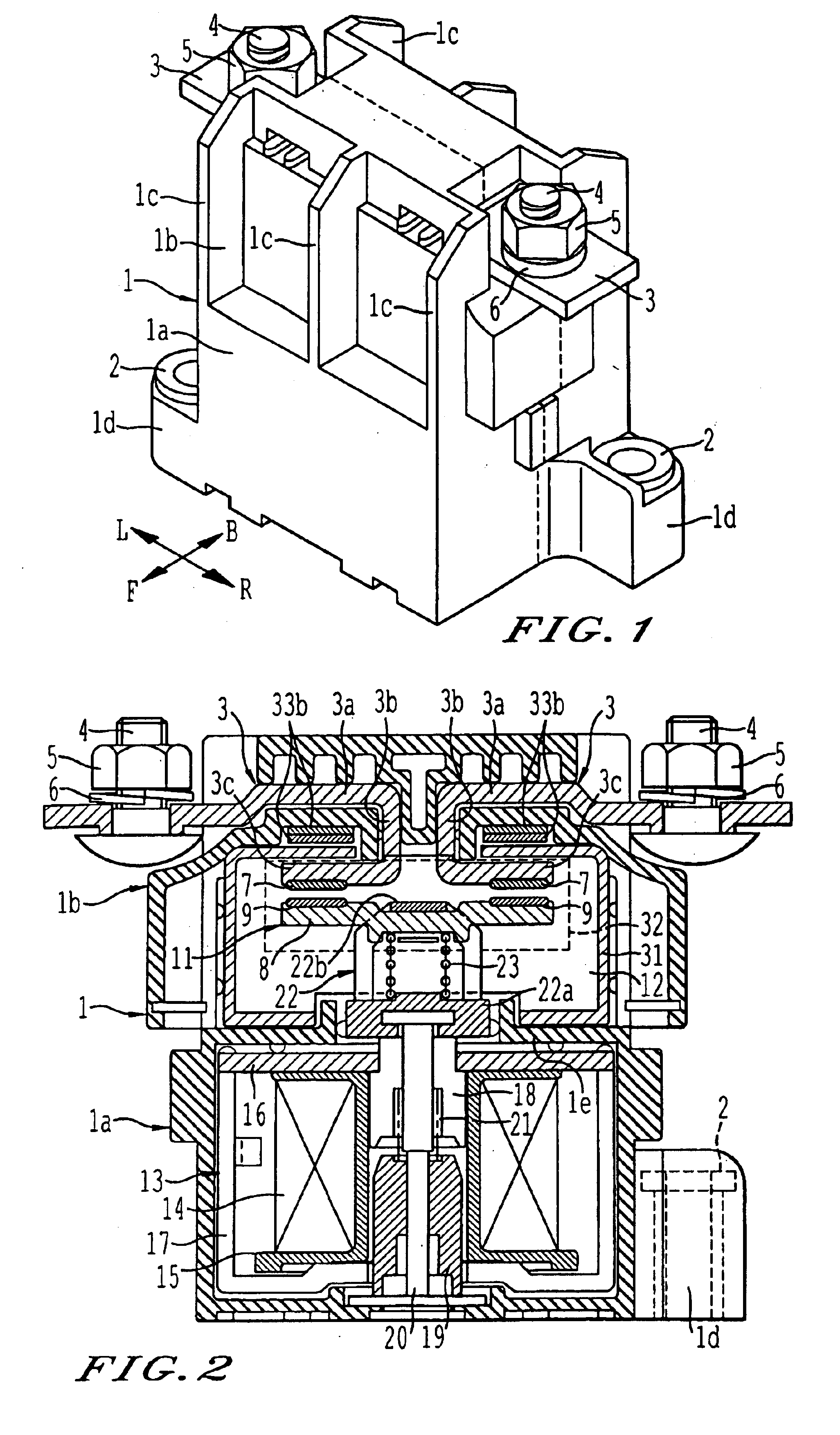
A contact apparatus according to this embodiment includes a housing 1 of an outward appearance shown in FIG. 1. The housing 1 comprises synthetic resin molded product. A lower half of the housing 1 is formed as a substantially rectangular parallelepiped lower housing portion 1a for accommodating a driving mechanism 13 therein, and an upper half is formed as an upper housing portion 1b for accommodating a current switching mechanism 11 which will be described later. A longitudinal thickness (in an F-B direction in the drawing) of the upper housing portion 1b is smaller than that of the lower housing portion 1a. Vertical wall-like ribs 1c . . . are formed on opposite ends and an intermediate portion in the lateral direction (in an L-R direction in the drawing) of front and rear wall surfaces of the upper housing portion 1b.

Fixing portions 1d and 1d are formed on a bottom of the lower housing portion 1a for fixing the contact apparatus. The fixing portions 1d and 1d project sideways (L...

embodiment 2

A contact apparatus according to another embodiment of the present invention will be explained with reference to FIG. 12. Members having the same functions as those of the contact apparatus of the previous embodiment 1 are designated with the same symbols, and detailed explanation thereof is omitted. The same is applied to the subsequent embodiments.

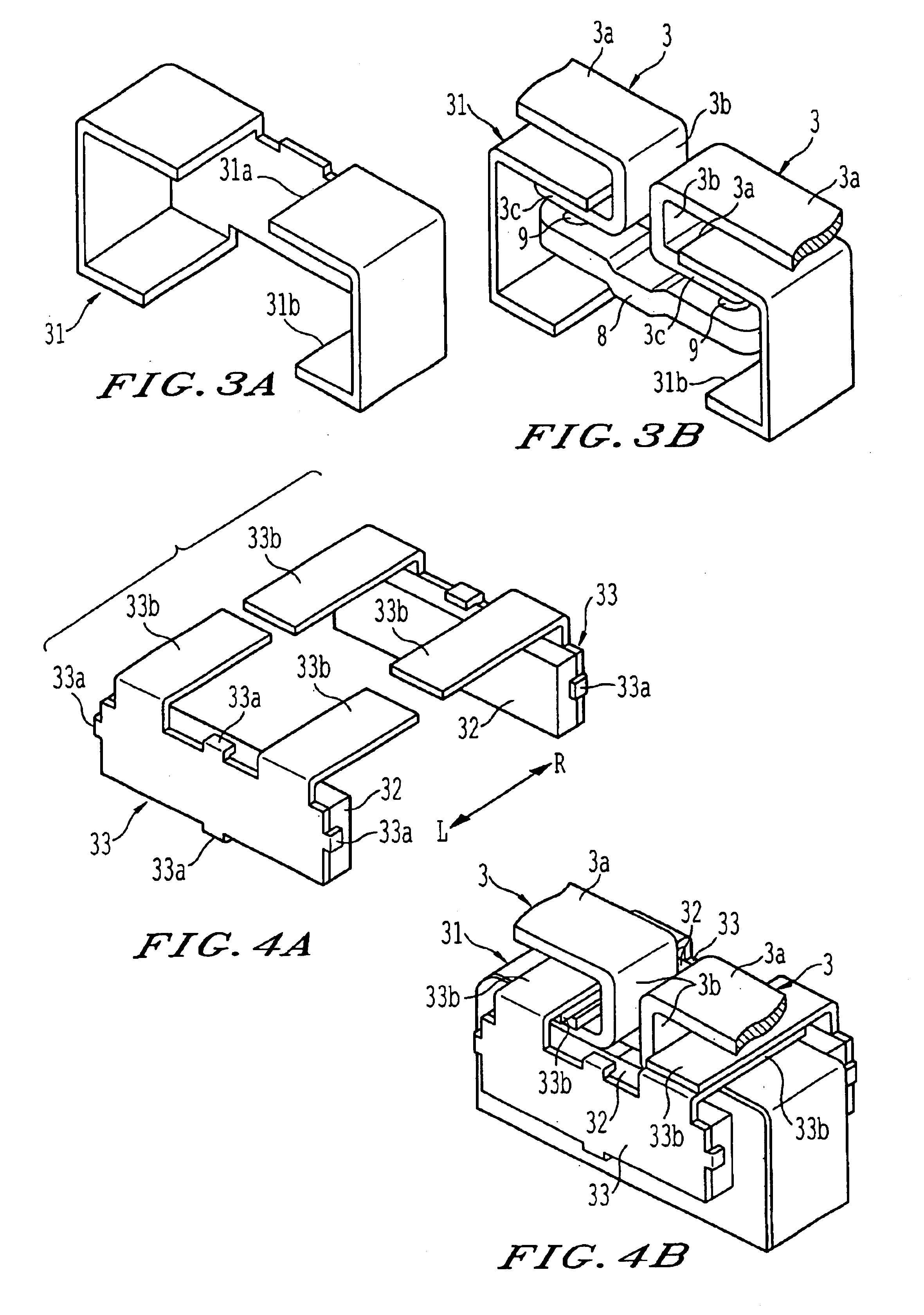
In this contact apparatus of the present embodiment, the pair of left and right fixing contact points 7 and 7 and the movable contact points 9 and 9 which are opposed to the former contacts from below are provided at locations closer to a center line of the housing 1 compared to that of the previous embodiment 1. With this structure, a length of each the contact fixing portion 3c from the fixing contact point 7 to the end is long, and this portion is formed as an arc running portion 3d. Similarly, the movable contact 8 is provided at outer sides from the mounted positions of the movable contact points 9 and 9 with long arc running portio...

embodiment 3

A contact apparatus of another embodiment of the present invention will be explained with reference to FIGS. 13 to 16.

As shown in FIG. 13, the housing 1 of this contact apparatus comprises the lower housing portion 1a and the upper housing portion 1b provided on the lower housing portion 1a. The upper housing portion 1b has a thickness in the longitudinal direction smaller than that of the lower housing portion 1a. However, the front and rear wall surfaces of the upper housing portion 1b are not provided with the ribs 1c . . . shown in FIG. 1, but are formed as flat surfaces. The permanent magnet 32 having the yoke 33 having the same shape as that of the previous embodiment is mounted to each of the surfaces from outside. That is, the upper housing portion 1b is formed with through holes in the longitudinal direction, and the magnetic path 33b of the yoke 33 passes through each of the through holes, and the pair of permanent magnets 32 and 32 are mounted to the upper housing portion...


PUM


Abstract

A contact apparatus is provided having a permanent magnet disposed in a region where a fixing contact point is mounted to a fixing contact and a movable contact to which a movable contact point is mounted. An arc generated between both the contact points is moved in a lateral direction by the magnetic force of the permanent magnet and stretched. An arc-extinguishing member which is heated by the arc for generating arc-extinguishing gas is provided such as to surround the fixing contact point and the movable contact point.

Description

The present invention relates to a contact apparatus suitable for a relay of a power load or an electromagnetic switch.Background TechniqueIn a contact apparatus used for opening and closing a power supply of an electrically running automobile, relatively great DC current as great as 100A is switched. In such a contact apparatus, it is difficult to swiftly break the current due to arc generated between contacts when an electric path is opened. Thereupon, Japanese Patent Application Laid-Open No. H8-45411 for example discloses a contact apparatus having an insulator which is heated by heat of an arc for generating arc-extinguishing gas, in which the arc is cooled by the arc-extinguishing gas, thereby enhancing the breaking performance.However, if the insulator for generating the arc-extinguishing gas is merely provided, a voltage rising speed of the arc generated between contacts is small, and there is a problem that excellent breaking performance can not always be obtained.The prese...

Claims


Application Information

Patent Timeline
Patent Type & Authority Patents(United States)
IPC IPC(8): H01H33/70H01H33/76H01H9/30H01H9/44H01H9/34
CPCH01H9/302H01H9/443H01H33/765H01H9/34H01H9/342H01H50/54
Inventor YAMAMOTO, RITSUSHIMOMURA, TSUTOMUUOTOME, RIICHIENOMOTO, HIDEKITOGUCHI, TAKEHIKOTATENO, MAMORUIWAMI, YOSHIYUKI
Owner MATSUSHITA ELECTRIC WORKS LTD
Why Eureka
Try Eureka