Anode of an arc plasma generator and the arc plasma generator

a plasma generator and anode technology, applied in the field of plasma, can solve the problems of increasing cost, electrical devices, increasing the demand of conventional arc plasma generators, etc., and achieve the effects of increasing the voltage of the plasma generator, increasing the total amount of wind, and lengthening the ar

Active Publication Date: 2014-04-15
YANTAI LONGYUAN POWER TECH
View PDF8 Cites 1 Cited by
  • Summary
  • Abstract
  • Description
  • Claims
  • Application Information

AI Technical Summary

Benefits of technology

[0031]After adopting above technical solutions, since the anode portions are connected electrically therebetween, the problem that the insulating connection between the anode portions causes too many fault points and affects arc stability is avoided. When the multi-stage gas admission type plasma generator of the present invention operates, the gas between the first anode portion and the cathode are broken down by high-voltage current to form a circuit, and an arc is generated. The arc moves to the next anode portion farther from the cathode under pull force of the primary gas admission supplied from near the cathode. At this time, the secondary gas admission is supplied tangentially to ensure the arc root does not fall to a next stage of arc channel, the arc will be lengthened step by step and so forth until to the last stage of the anode. The voltage of the plasma generator is increased by lengthening the arc. Since the multi-stage gas admission are supplied in the tangential direction, a good wind field is organized, and the total amount of wind is increased greatly, the distance between actual discharge positions of the anode and the cathode is increased, and the length of the arc is enlarged, the output voltage of the generator is increased, and the power of the plasma generator is improved at a defined input current.

Problems solved by technology

However, with the demand on temperature of arc plasma jet flow in new application fields becoming higher and higher, conventional arc plasma generator cannot satisfy its demand any more.
If the method of increasing the current of the arc plasma generator is adopted, the requirement to the electrical device is strict and the cost is increased, and this method will cause more burning damage to electrode, and will shorten the service life of the anode and cathode of the arc plasma generator.
However, it is difficult to achieve the goal due to the limit of the single stage of anode gas admission structure.
However, the operating process is relatively complicated as the plasma generator relates to switching the switches during the operating process.
Since the anode insulating connection of the generator is of relatively complicated structure, there are too many fault points, and the operation is complicated.
And the arc transferring will succeed only after the operation is operated several times, the reliability of the device is affected.
Though the dual-anode plasma generator in the prior art can improve the wind field in the generator by two-stage gas admission, lengthen the plasma arc and improve the power of the plasma, the anode insulating connection in the generator renders the structure relatively complicated, too many fault points and complicated operation.
And the process will succeed only until the operation is operated several times, the reliability of the device is affected.
When the generator operates, dual-arc phenomena (that is, there exist plasma arcs between the cathode and each stage of the anode) occurs frequently, the insulating material between the stages of the anodes is burned out, and safety of the device is affected.

Method used


Image

  • Anode of an arc plasma generator and the arc plasma generator
  • Anode of an arc plasma generator and the arc plasma generator
  • Anode of an arc plasma generator and the arc plasma generator

Examples


embodiment 1

[0052]

[0053]FIG. 7 is a structure diagram of an arc plasma generator of hot cathode type formed by an anode of two-stage gas admission.

[0054]Wherein 701 is a tip emitting cathode, 702 is a gas ring, 703 is a spiral gas flow formed by the first-stage gas admission after it passes by the gas ring 702, 704 is a first anode portion, 705 is a spiral gas flow by the second-stage gas admission after it passes from the gas guiding holes 708 by a flow guiding groove 709, 706 is a second anode portion, 707 is a movement track of the arc, 708 are gas guiding holes, and 709 is a flow guiding groove.

[0055]FIG. 7b is a section view along plane A of the gas ring 702 in FIG. 7, wherein the gas ring 702 is made of an isolation material to avoid a short circuit between the cathode 701 and the first anode portion 704, the gas guiding holes in the gas ring 702 can be tangential holes, or the gas guiding holes that cause the direction of gas velocity to possess tangential and axial vectors simultaneousl...

embodiment 2

[0062]

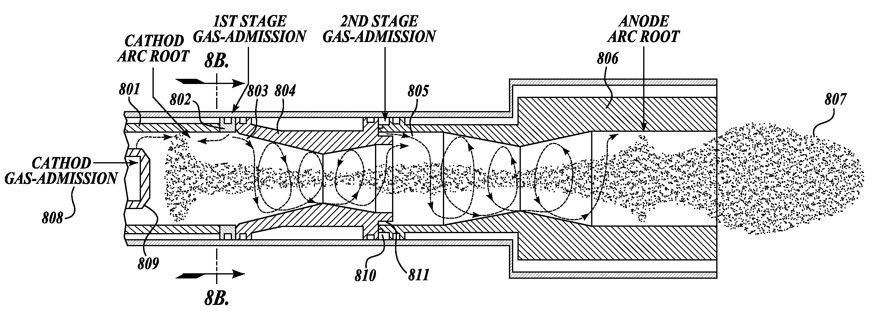
[0063]FIG. 8 is a structure diagram of an arc plasma generator of cold cathode type formed by an anode of two-stage gas admission.

[0064]Wherein 801 is a tubular cathode, 802 is a gas ring, 803 a spiral gas flow formed by the first-stage gas admission after it passes by the gas ring 802, 804 is a first anode portion, 805 is a spiral gas flow formed by the second-stage gas in take after it passes by a flow guiding groove 811 from the gas guiding holes 810, 806 is a second anode portion, 807 is a movement track of the arc, 808 is a cathode gas admission, 809 is a gas ring for the cathode gas admission, 810 are gas guiding holes, and 811 is a flow guiding groove.

[0065]FIG. 8b is a section view of the gas ring 802 shown in FIG. 8, the gas ring 802 is a tangential gas ring. Wherein the gas ring 802 is made of an isolation material to avoid a short circuit between the cathode 801 and the first anode portion 804, the gas guiding holes in the gas ring 802 are tangential holes. The gas ...


PUM


Abstract

An anode of an arc plasma generator and the arc plasma generator are disclosed. The plasma generator is a multi-stage gas admission type arc plasma generator, and the plasma generator includes a cathode and an anode. The anode comprises at least two portions (201, 203), wherein any two adjacent portions of the anode are connected electrically with one another.

Description

[0001]The present application is the National Stage application of PCT / CN2010 / 070250, filed Jan. 19, 2010, which claims the benefit of Chinese application No. 200910014106.6, filed on Jan. 19, 2009. The disclosure of each application is incorporated herein by reference in its entirety.TECHNICAL FIELD[0002]The present invention generally relates to the technical field of plasma, and more specifically, to an anode of an arc plasma generator and the arc plasma generator.DESCRIPTION OF RELATED ART[0003]Recently, since arc plasma as a special hot source is applied more and more widely, arc plasma technique is developed rapidly. However, with the demand on temperature of arc plasma jet flow in new application fields becoming higher and higher, conventional arc plasma generator cannot satisfy its demand any more. In order to satisfy the demand, an arc plasma generator with simple structure and higher output power is needed to be developed in urgency. There are mainly two methods to increas...

Claims


Application Information

Patent Timeline
Patent Type & Authority Patents(United States)
IPC IPC(8): H01J17/26
CPCH05H2001/3431H05H1/34H05H1/3431
Inventor WANG, YUPENGLI, YIYANG, SHUOYANG, JINHUA
Owner YANTAI LONGYUAN POWER TECH
Why Eureka
Try Eureka