Traffic shaper

a shaper and traffic technology, applied in the field of traffic shapers, can solve the problems of not considering the traffic characteristics, not performing the shaping cell intervals for each virtual path or virtual channel, and not improving the coefficient of utilization of network resources

Inactive Publication Date: 2004-03-09
JUMIPER NETWORKS INC
View PDF25 Cites 105 Cited by
  • Summary
  • Abstract
  • Description
  • Claims
  • Application Information

AI Technical Summary

Benefits of technology

Furthermore, the present invention aims to provide a traffic shaper in which traffic-shaping is performed by considering the priority of each virtual path or virtual channel based on the cell delay variation tolerance, that is one of the traffic characteristics, for more decreasing the cell delay variation of a virtual path or a virtual channel, in which a small cell delay variation tolerance is defined, in comparison with the cell delay variation of a virtual path or a virtual channel, in which a large cell delay variation tolerance is defined.
Furthermore, the present invention aims to provide a traffic shaper in which traffic-shaping is performed by considering the priority of each virtual path or virtual channel based on a peak cell rate (PCR), that is one of the traffic characteristics, for more decreasing the cell delay variation of a virtual path or a virtual channel, in which a cell flow of a large peak cell rate is contained, in comparison with the cell delay variation of a virtual path or a virtual channel, in which a cell flow of a small peak cell rate is contained.

Problems solved by technology

But, they are not considering the traffic characteristics of the virtual path or virtual channel in their control.
There was therefore a problem that shaping cell intervals for each virtual path or virtual channel was not performed.
Besides, there was a problem that the coefficient of utilization of the network resources was not improved because no consideration was made for sending out cells by a priority order depending on allowable values of cell delay variation for a virtual channel.

Method used


Image

  • Traffic shaper
  • Traffic shaper
  • Traffic shaper

Examples


first embodiment

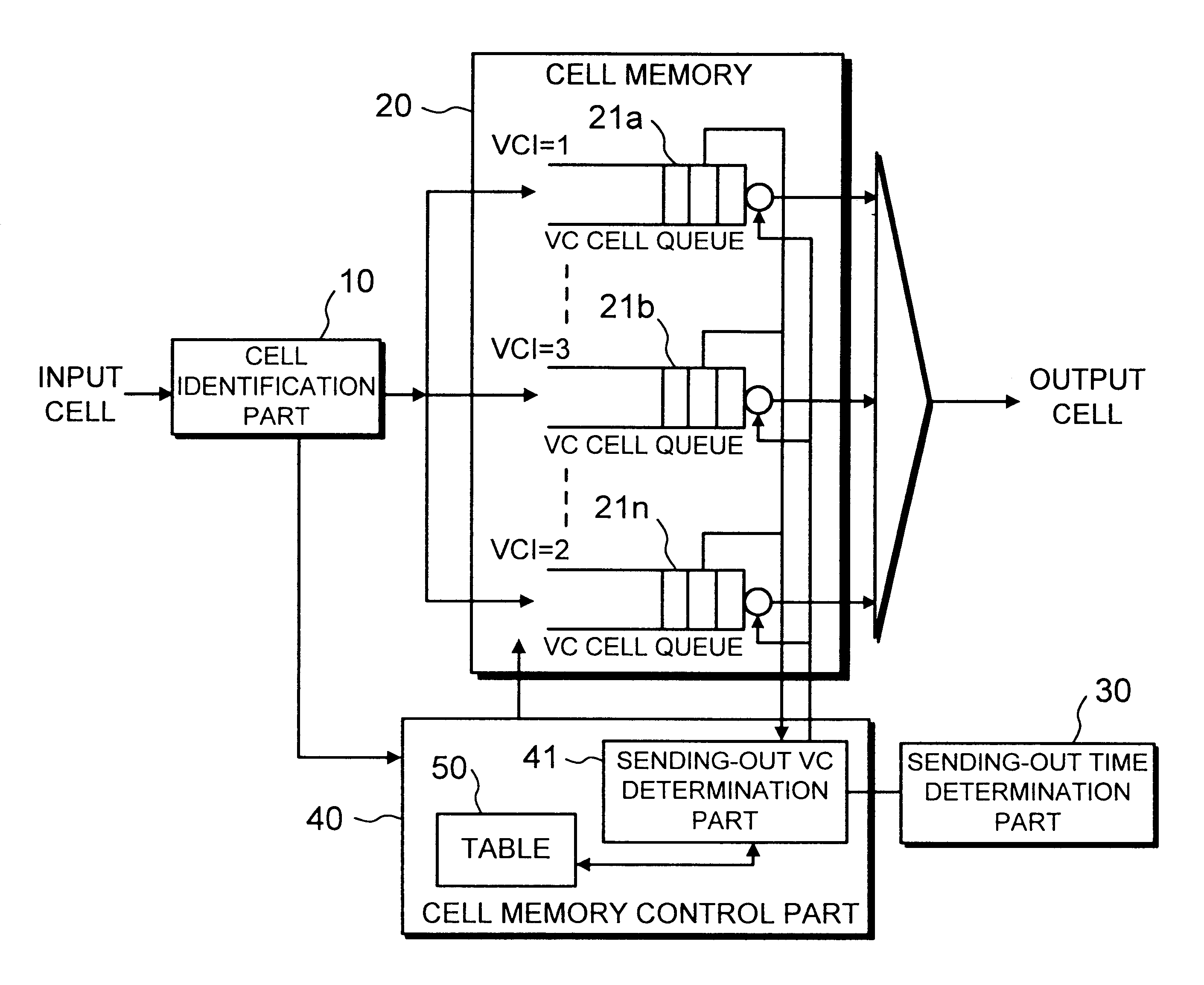
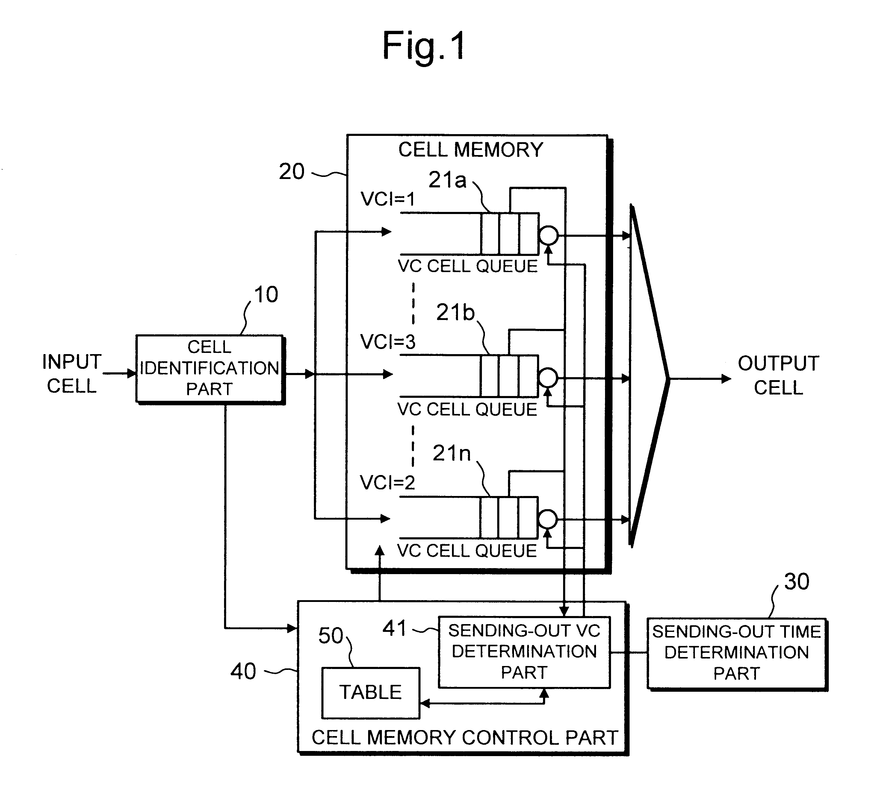
Next, the operation of the present invention will be described in detail with reference to the drawings. Referring to FIG. 4, when a virtual connection is newly established, the reading-out priority is determined so that the smaller the CDVT of the virtual connection is, the higher the reading-out priority is. The priority table 51 is then renewed. In FIG. 4, a younger priority number is given to a higher reading-out priority virtual connection.

Referring to FIGS. 1, 4 and 5, when a cell arrives this traffic shaper, after the virtual connection of the cell is identified by the cell identification part 10, the cell is stored in the corresponding queue of virtual connection among the VC cell queue 21a-n. Upon storing, if the empty flag of the corresponding virtual connection of the sending-out time schedule / buffer state table 52 is empty (E), it is changed to full (F).

The stored cell is read out from the VC cell queue under instructions by an output competition control operation of the...

second embodiment

Next, the present invention will be described in detail with reference to the drawings.

The construction of the second embodiment is the same as that of the first embodiment of the present invention shown in FIG. 1, so the description is omitted. It means that the priority table 51 and the sending-out time schedule / buffer state table 52 are also provided for the second embodiment. And also, operations shown in FIG. 7 and FIG. 8 are applied in the same manner as the first embodiment.

FIG. 10 is a flow chart showing a selection process of a virtual connection for which a cell is to be sent out of the second embodiment of the present invention. Referring to FIG. 10, a point of difference from the operation of the first embodiment of the present invention shown in FIG. 9 is the point in which a process (step S407) that the priority of the selected virtual connection, for which an operation of a cell sending-out has been completed, is renewed to the lowest position among the group of virtu...

third embodiment

Next, the present invention will be described in detail with reference to drawings.

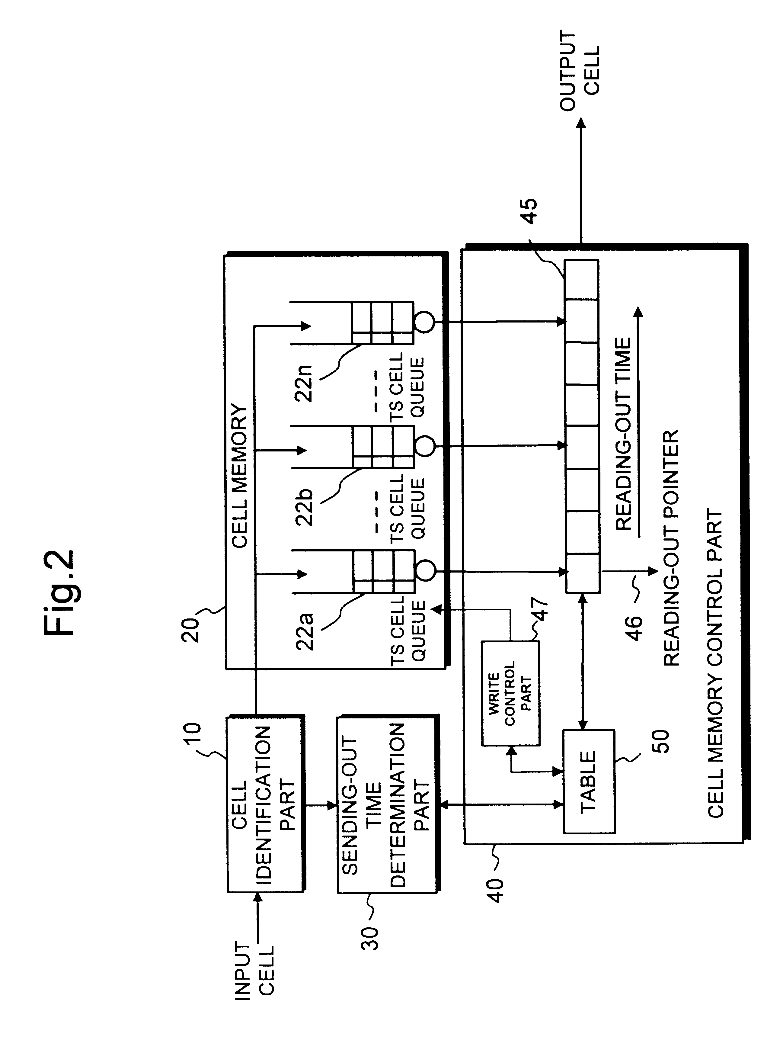
FIG. 2 is a block diagram showing the construction of a traffic shaper that is the third embodiment of the present invention. In FIG. 2, parts same as or similar to those of the above FIG. 1 are denoted by the same references. Referring to FIG. 2, the third embodiment of the present invention comprises a cell identification part 10, a cell memory 20, a sending-out time determination part 30 and a cell memory control part 40.

The cell memory 20 comprises a time slot (TS) cell queue 22a-n that is a virtual queue for each sending-out scheduled time.

The cell memory control part 40 comprises a table 50, reading-out time slots 45 corresponding to sending-out scheduled times, a reading-out pointer 46 and a write control part 47. Hereinafter, the detail of the structure of the table 50 will be shown.

FIG. 6 is an explanatory view showing an example of a time slot / buffer state table 53 provided in the third embo...


PUM


Abstract

A traffic shaper for absorbing a cell delay variation of cell flow in each of virtual connections in an ATM (asynchronous transmission mode) network is realized. The traffic shaper comprises a cell identification part, a cell memory, a sending-out time determination part and a cell memory control part. The cell identification part is provided for identifying a virtual connection allocated to an input cell, the cell memory is provided for storing input cells into respective virtual queues, each queue is corresponding to the virtual connection, in accordance with the identified virtual connection of each input cell, the sending-out time determination part is provided for determining a sending-out time for each cell stored in the cell memory on the virtual connection basis, and the cell memory control part is provided for performing a cell output from each virtual queue in accordance with the sending-out time determined for each cell, and performing an output competition control by selecting a cell to be output among cells having the same sending-out time in different virtual queues in accordance with a predetermined output priority assigned to each virtual connection.

Description

1. Field of the InventionThe present invention relates to a traffic shaper for absorbing the cell delay variation in virtual paths (Virtual Path: VP) and virtual channels (Virtual Channel: VC) in an ATM (asynchronous transmission mode) network.2. Description of the Related ArtData to be transmitted is devided into a plurality of fixed-length packets, each packet is called "a cell", and those cells are transmitted in the ATM network. On a physical transmission line of the ATM network, virtual paths and virtual channels are defined for each of connections, and cells on virtual channels are multiplexed and transmitted on a virtual path.As cells are multiplexed asynchronously, when cells pass through a multiplexing apparatus, a switch apparatus and so on, a cell delay variation (hereinafter called CDV) occurs due to the deference of queueing time in buffers in each apparatus. The CDV may cause to generate cells, each having a small cell interval, and as the result, the traffic becomes a...

Claims


Application Information

Patent Timeline
Patent Type & Authority Patents(United States)
IPC IPC(8): H04L12/56H04L47/22H04Q3/00H04L47/6275H04L49/9023
CPCH04L12/5601H04L2012/5649H04L2012/5651H04L2012/5679H04L2012/568H04L2012/5681
Inventor KAMIYA, SATOSHI
Owner JUMIPER NETWORKS INC
Why Eureka
Try Eureka