
Payload mapping in synchronous networks

a payload mapping and synchronous network technology, applied in data switching networks, time-division multiplexing selection, multiplex communication, etc., can solve the problems of high packetization header overhead, e1, e3, and frame-based datacoms data rates are not well matched to conventional telecoms data rates

Inactive Publication Date: 2004-03-09
RPX CLEARINGHOUSE
View PDF13 Cites 38 Cited by
  • Summary
  • Abstract
  • Description
  • Claims
  • Application Information

AI Technical Summary

Benefits of technology

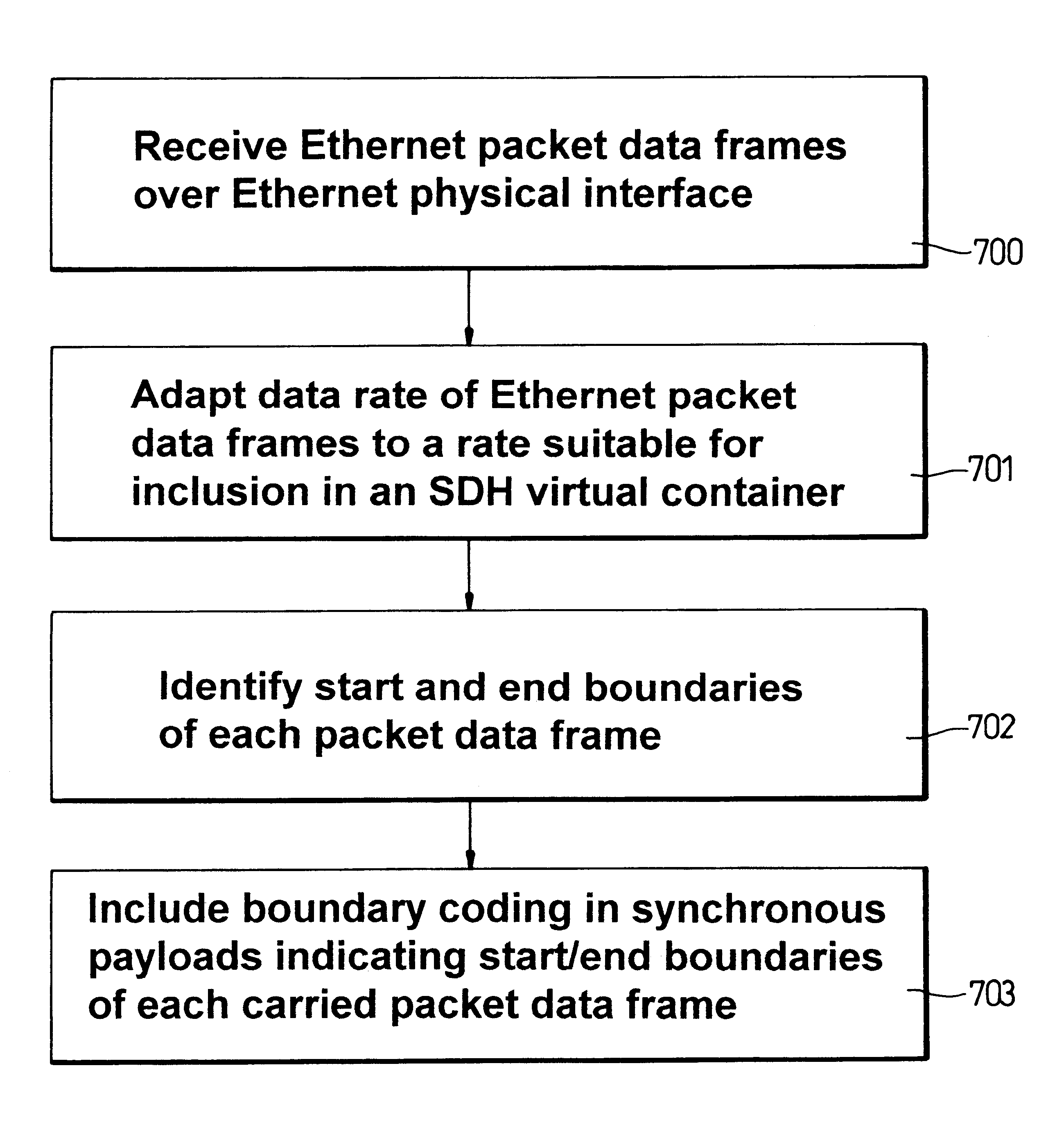
"The present invention relates to a method for efficiently mapping datacoms data, such as Ethernet data, into a synchronous digital network. The invention allows for the incorporation of frame based data into a synchronous digital network with a minimum of delay and protocol header overhead. The method involves encoding at least one packet data frame with a code that designates a boundary of the frame, and then inputting the encoded frame into a synchronous data channel. The invention also allows for the multiplexing of multiple frame based data channels into a synchronous digital network channel. The technical effects of the invention include efficient mapping of datacoms data into a synchronous digital network and minimization of delay in containing the data in synchronous containers."

Problems solved by technology

In order to accommodate datacoms frame based data, which is characterized by its own set of data rates and control data characteristics, and to contain such frame based data in conventional synchronous digital networks, there is a problem that the frame based datacoms data rates are not well matched to conventional telecoms data rates, for example E1, E3, T1, STM-1 data rates.
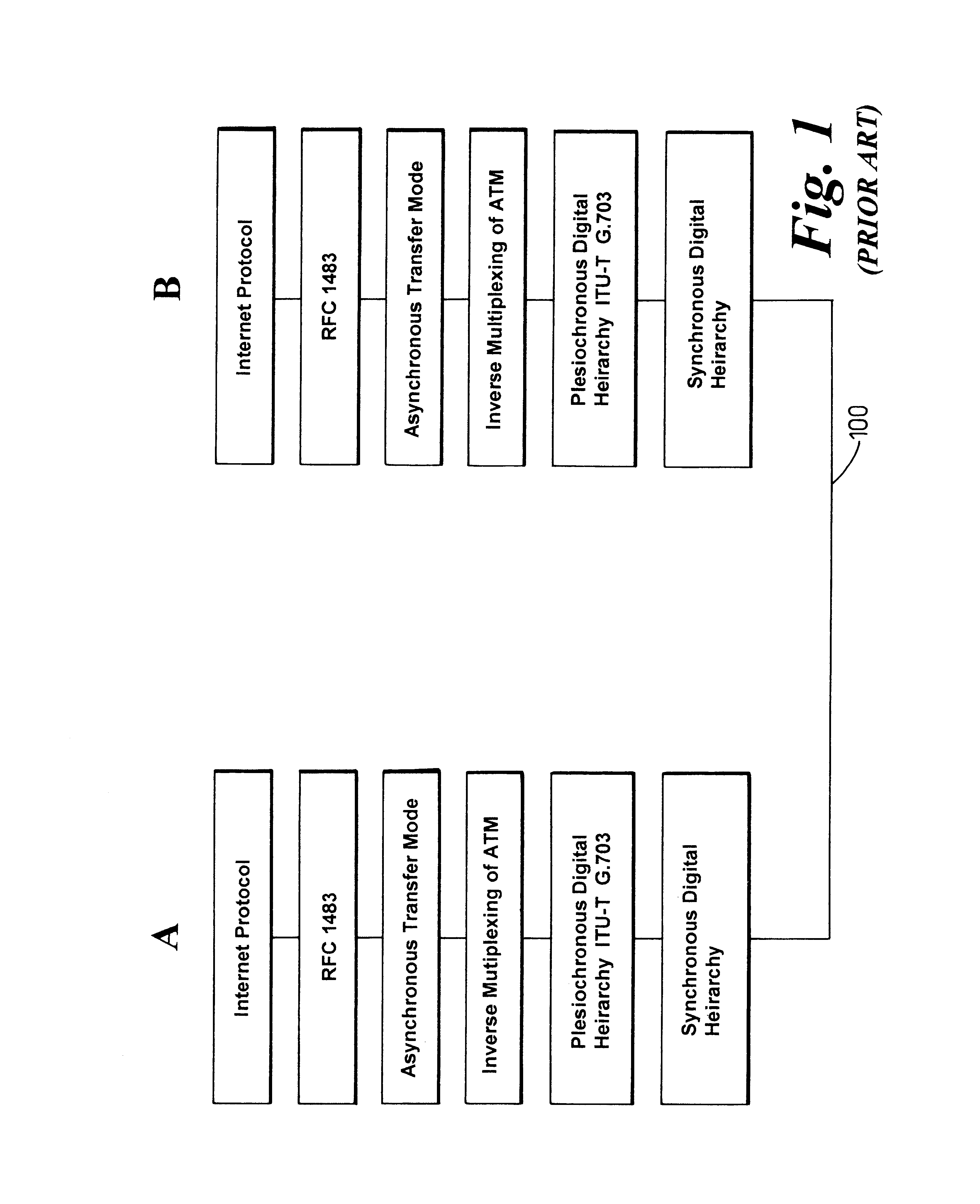
However, this prior art scheme has a disadvantage of a high packetization header overhead, which can comprise up to 20% of the SDH payload.
Each layer of packetization and encapsulation also adds delay to the data traffic carried.
However, in each of these schemes, a high packetization overhead is present and packaging delays are relatively high, which slows down passage of datacoms data through a network.

Method used


Image

  • Payload mapping in synchronous networks
  • Payload mapping in synchronous networks
  • Payload mapping in synchronous networks

Examples


Embodiment Construction

There will now be described by way of example the best mode contemplated by the inventors for carrying out the invention. In the following description numerous specific details are set forth in order to provide a thorough understanding of the present invention. It will be apparent however, to one skilled in the art, that the present invention may be practiced without limitation to these specific details. In other instances, well known methods and structures have not been described in detail so as not to unnecessarily obscure the present invention.

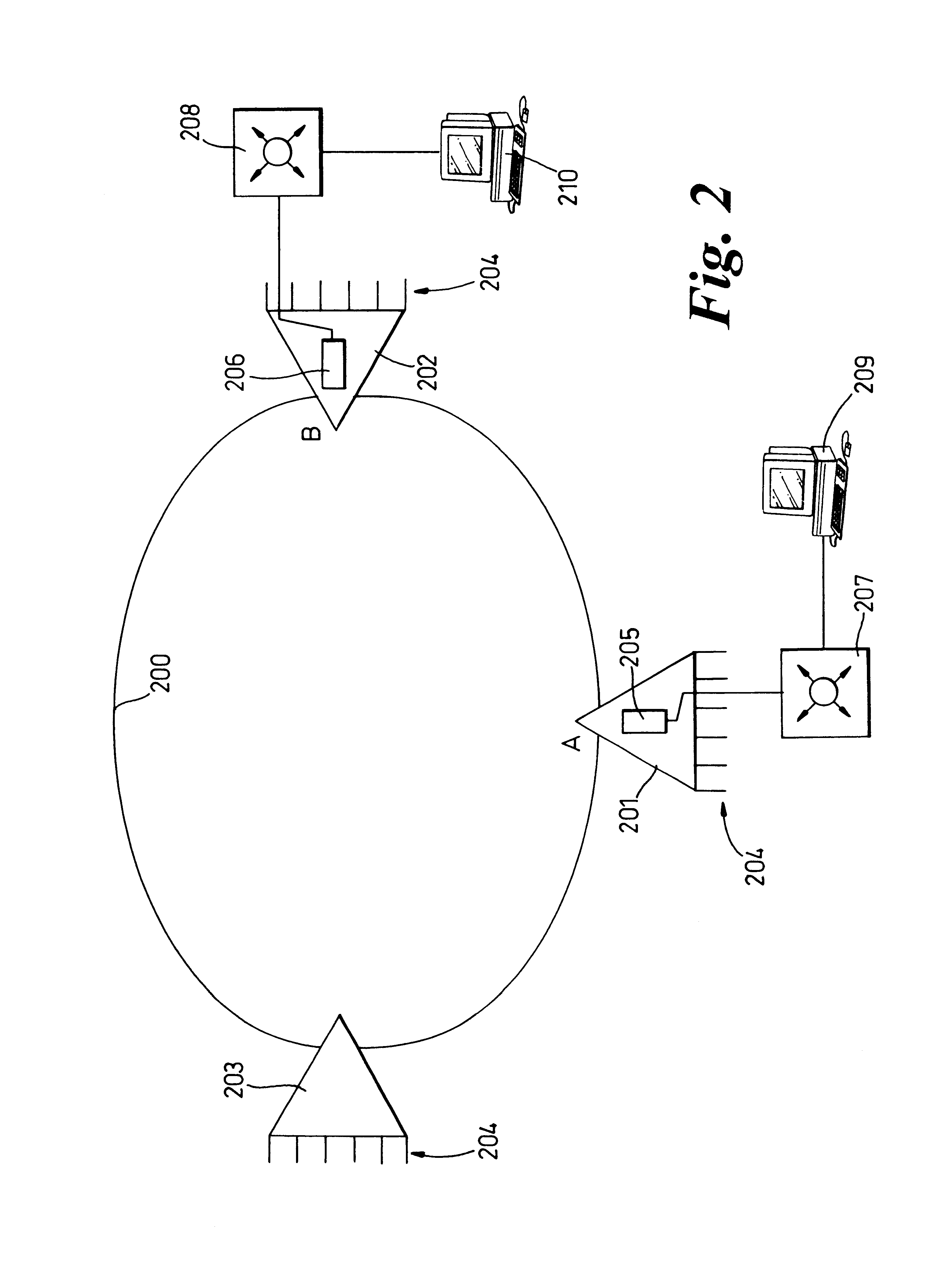
Referring to FIG. 2 herein, there is illustrated schematically a section of a synchronous digital hierarchy (SDH) network comprising an STM-fiber ring 200 connecting a plurality of add-drop multiplexers 201-203, each multiplexer having a plurality of telecoms tributaries 204, for example E1 tributaries operating at 2 MBits / s, first and second multiplexers 201, 202 respectively at first and second locations A, B, each comprise a correspondin...


PUM


Abstract

There is disclosed a method of carrying frame based data, eg Ethernet data, over a synchronous digital hierarchy network in order to provide local area network type functionality over a wide area network coverage. Specific embodiments disclose methods of mapping Ethernet data frames into SDH virtual containers, and distinguishing start and end boundaries of the Ethernet data frames within the virtual container payloads, by a selection of encoding methods including a segmentation, pointer methods, bit stuffing methods and byte stuffing methods. Data frames are encoded with a code which designates a boundary of each frame, and the encoded frames are input into a synchronous data channel.

Description

The present invention relates to synchronous networks, and to the carrying of frame based data over synchronous networks.BACKGROUND TO THE INVENTIONIn the applicant's co-pending patent application entitled "Frame Based Data Transmission over Synchronous Digital Hierarchy Network" filed contemporaneously with the present application, and a copy of which is filed herewith, there is disclosed a method of carrying frame based data over a synchronous digital network. Such disclosed system may provide OSI layer 2 switching functionality which was only previously available in prior art local area networks, but extended over a geographical coverage area which has been historically considered to have been provided only by prior art wide area networks.In order to accommodate datacoms frame based data, which is characterized by its own set of data rates and control data characteristics, and to contain such frame based data in conventional synchronous digital networks, there is a problem that t...

Claims


Application Information

Patent Timeline
Patent Type & Authority Patents(United States)
IPC IPC(8): H04J3/16H04Q11/04
CPCH04J3/1617H04Q11/0478H04J2203/0076H04J2203/0082H04J2203/0089Y10S370/907
Inventor RUSSELL, JOHN PAULMURTON, CHRISTOPHER DAVIDGOODMAN, DAVID MICHAELRAMSDEN, CHRISTOPHERSHIELDS, JAMES
Owner RPX CLEARINGHOUSE
Learn More