Single point mooring with suspension turret

a single-point mooring and suspension turret technology, applied in the field of mooring systems, can solve the problems of reducing the efficiency of the interface, requiring additional cost, and reducing the efficiency of the motion interface by as much as fifty percen

Inactive Publication Date: 2004-03-23
SOFEC
View PDF17 Cites 12 Cited by
  • Summary
  • Abstract
  • Description
  • Claims
  • Application Information

AI Technical Summary

Benefits of technology

Another object of the invention is to provide a turret support system which increases tolerance to radial misalignment between the center of the lower bearing and upper bearing.
Another object of the invention is to provide a turret support system which increases tolerance to circumferential misalignment while maintaining a uniform sharing of load among all load-bearing elements.
The objects identified above along with other advantages and features are incorporated in a system which suspends a single point mooring turret from bogie wheels which are arranged to roll along a rail of the FPSO hull. The system utilizes a pendular suspension system including rocker beams carried by the bogies which help transfer a circumferentially uniform axial load without moment through the interface of motion between the vessel and turret, by decoupling system loads, inertial loads, and hull deflection induced loads across that interface. The bogies are seated on a rail which allows the bogies to roll about the circumference of the moon pool. Suspending the turret from the bogies decouples radial hull deflections due to ovality, because the rail is not connected rigidly to the turret in the radial direction. A set of bogie rocker beams is coupled to the bogies. The bogie rocker beams are coupled to a set of turret rocker beams which are coupled to the turret. In one embodiment the turret is suspended via chains, cables, rods, columns, or the like between the bogie rocker beams and the turret rocker beams. In another embodiment, the turret is directly connected to the turret rocker beams. The rocker beams have equal arm lengths, and thereby equally share the vertical load imparted to any one bogie, thus reducing any moment on the bogies. Moments induced by the mooring system or inertial moments are counteracted via radial rollers or sliding bearings at the deck edge and bottom edge of the turret / vessel interface. The radial rollers or sliding bearings also provide vertical stability and centering of the turret within the moon pool.

Problems solved by technology

The moments and loads exerted on the bearings, bogies, or sliding element system reduce the efficiency of the interface and require additional cost to accommodate loads imparted by the interface itself which does not contribute directly to station keeping or riser support.
These moments, deflection, and misalignment problems are common to single point mooring turrets of all sizes, which have a rigid turret connected to a deflecting hull, and depending on the method used for their remediation, they can result in a reduction in efficiency of the motion interface of as much as fifty percent.
As the diameter of the turret increases, the material remaining in the hull outside the moon pool decreases, further exacerbating hull deflection problems at the hull-turret interface.
A second problem is the lack of machining capability in diameters large enough to accommodate a large size turret necessary for running as many risers as possible from the sea floor to a FPSO.
If bogie wheels (or simply "bogies") are connected to the rigid structure, at both the hull and turret side of the interface, any vertical deformation of the interface results in some bogies carrying more loads than their neighbors do.
In practice for very large turrets, such parallel plane condition is impractical to achieve especially during operation at sea.
They require precise machining, sealing and are still subject to deflection of the moon pool in the radial direction due to ovality.

Method used


Image

  • Single point mooring with suspension turret
  • Single point mooring with suspension turret
  • Single point mooring with suspension turret

Examples


Embodiment Construction

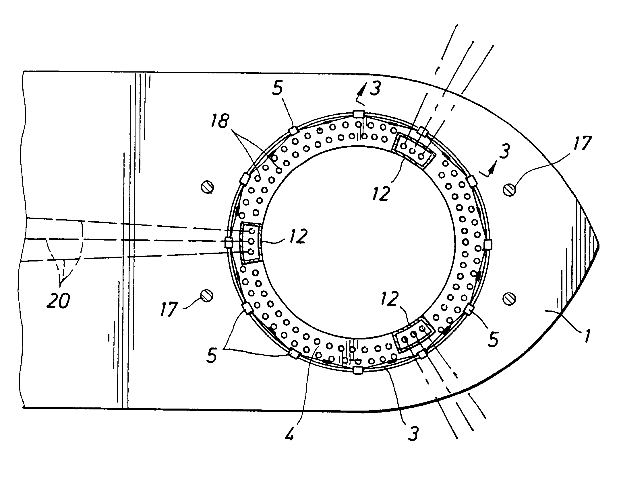
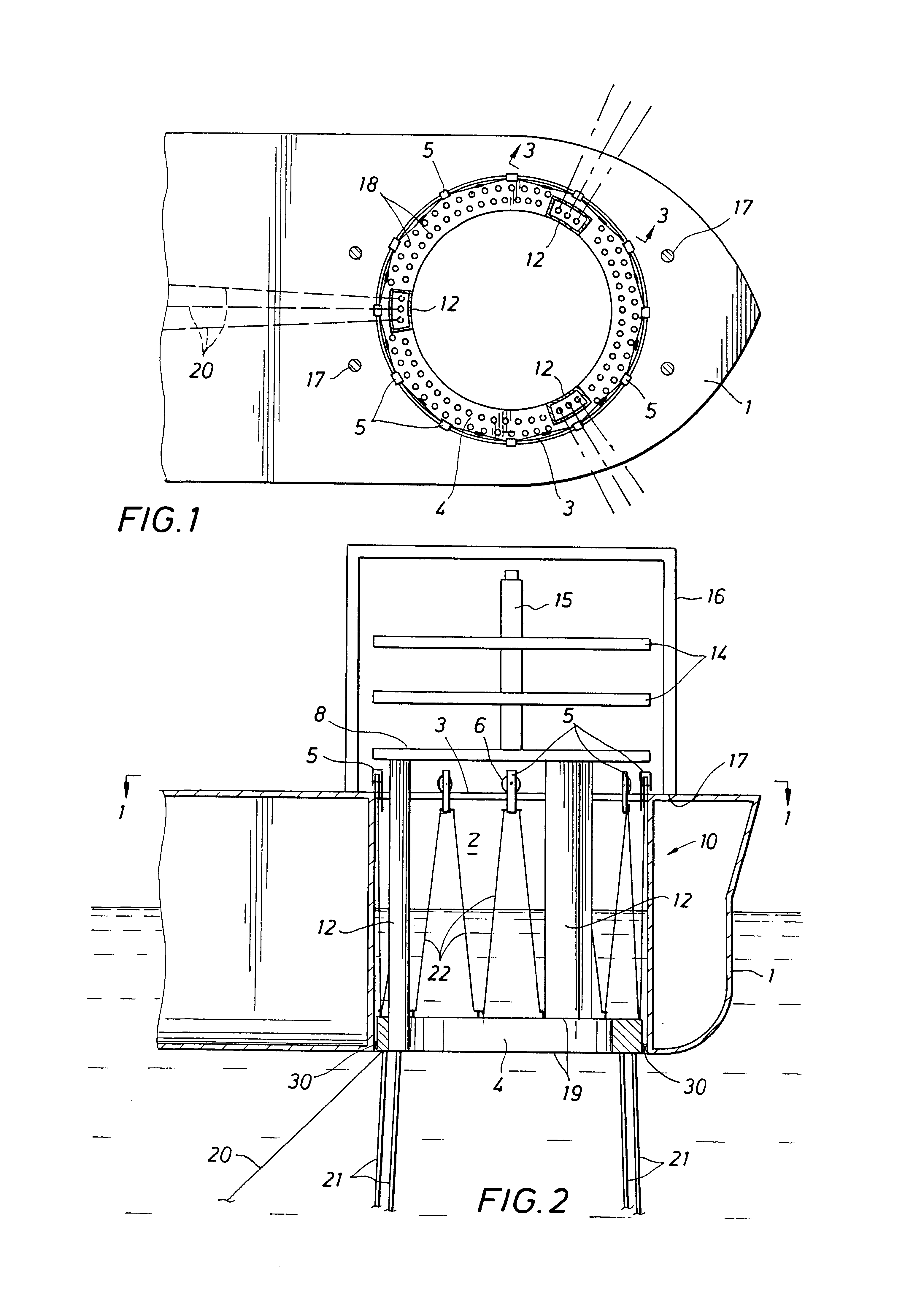
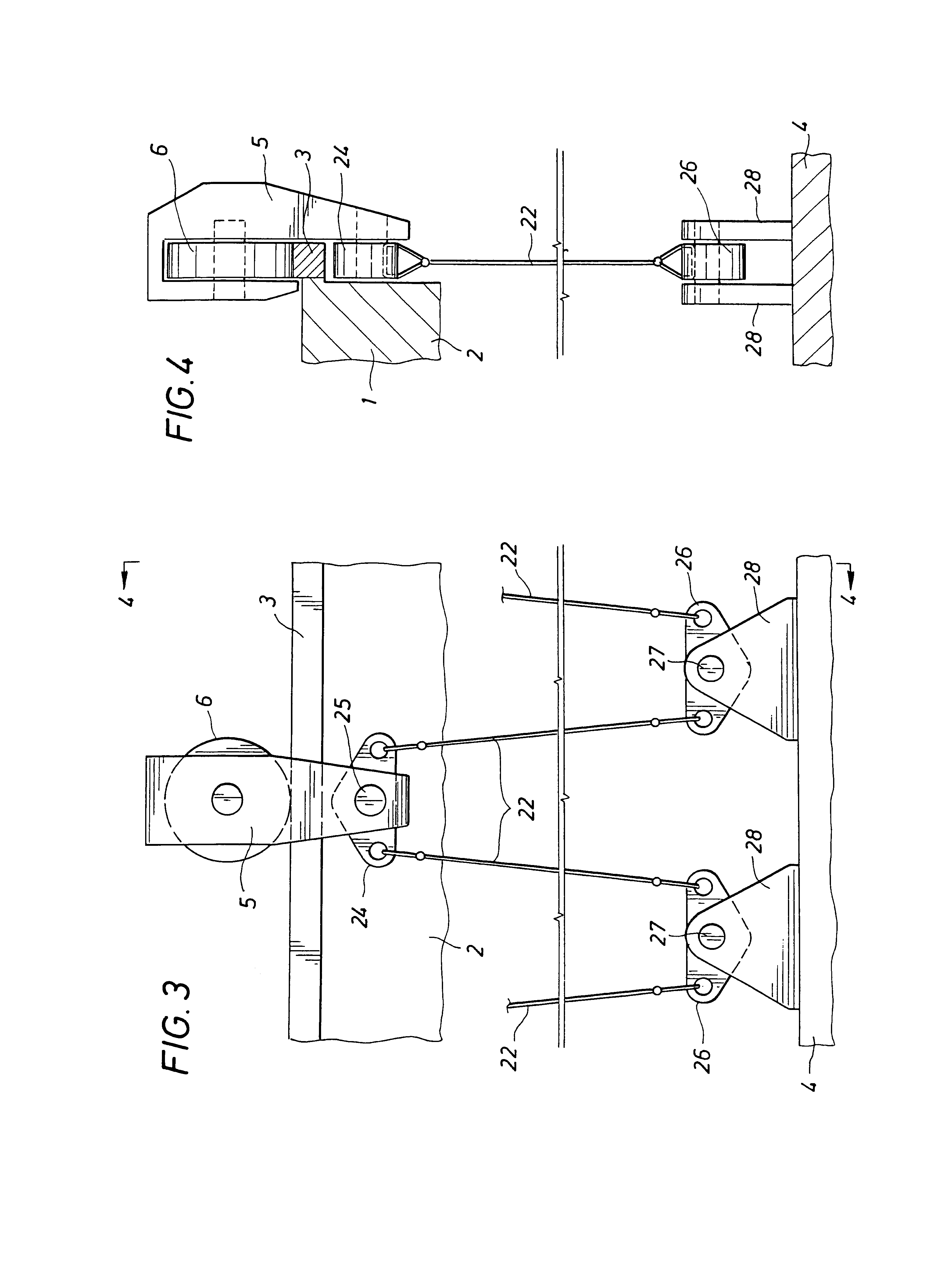
FIGS. 1 and 2 illustrate an embodiment of the invention in plan and profile views of the structural and mechanical arrangement of the suspension turret 10. The structural and mechanical arrangement supports a Single Point Mooring Turret 4 through a pendular suspension system consisting of bogie housings 5, or "bogies", having one or more wheels 6 per bogie 5, arranged to roll around the circumference of the moonpool on cambered or dished (not shown) rails 3. The rails 3 allow the bogies 5 to move in the radial direction while supporting their vertical loads, without substantially increasing radial loads thereby decoupling the bearing loads from radial hull deflections due to ovality. Radial flexure is achieved by hanging the turret 4 from the bogies 5 via suspension members 22 such as chains, cables, rods, columns, or the like, between the bogies 5 and riser support structure 19 of turret 4, such that the bogies 5 are not rigidly connected to the turret 4 in the radial direction.

FIG...


PUM


Abstract

An arrangement for suspending a Single Point Mooring Turret from its corresponding vessel, by transmitting a circumferentially uniform axial vertical load without moment through the interface of motion between the vessel and turret, by decoupling mooring system loads, inertial loads and hull deflection induced loads, from transmission across that interface. The arrangement supports the turret through a pendular suspension system which includes bogies, having one or more wheels or rollers per bogie, which roll around the circumference of the moonpool on a rail to allow the bogies to rotate in a horizontal plane which is perpendicular to the center line of the moonpool, and to decouple the bearing loads from radial hull deflection due to ovaling caused by rough seas. Radial flexure is achieved by suspending the turret from the bogie through rocker arms and chains, cables, rods or columns between the bogies and a riser support structure of the turret.

Description

1. Field of the InventionThis invention relates generally to mooring systems for offshore vessels and Floating Production Units ("FPUs") such as Floating Storage and Offloading vessels ("FSOs"), Floating Production Storage and Offloading vessels ("FPSOs"), Floating Storage Drilling Production and Drilling Units ("FPDSOs") and in particular to turret mooring arrangements or systems where a turret is rotatably supported on the vessel, and where the turret is fixed to the sea bed by anchor legs so that the vessel can weathervane about the turret.2. Description of the Prior ArtSingle point mooring systems using bearings, bogies, sliding elements and hydrostatic bearings at the interface of the motion between the geostationary turret and weathervaning hull are commonplace. Typically, the turret is a rigid tubular structure which transfers not only axial (vertical) loads from the mooring legs and risers, suspended therefrom, but also moments induced by mooring leg loads, hull deflections ...

Claims


Application Information

Patent Timeline
Patent Type & Authority Patents(United States)
IPC IPC(8): B63B21/00B63B21/50
CPCB63B21/507
Inventor COTTRELL, ROY H.BOATMAN, L. TERRY
Owner SOFEC
Why Eureka
Try Eureka