Ice composite body and process for the construction thereof

a composite body and composite technology, applied in the field of ice composite bodies, can solve the problems of large quantities of dissolved gas and liquid inclusions trapped in the ice, ice to be unstable under stress, ice to tend to creep, etc., and achieve the effect of convenient maintenan

Inactive Publication Date: 2004-03-30
MCALISTER PADRAIG
View PDF11 Cites 36 Cited by
  • Summary
  • Abstract
  • Description
  • Claims
  • Application Information

AI Technical Summary

Benefits of technology

Thus, according to the present invention there is provided an ice composite body for use in the construction of fixed or floating structures located in or on water, the body comprising an inner ice constrained core, a protective outer armour shell having side sections and a separate top section, the top section resting freely between the side sections on the ice core in use and being free to move vertically in use, such that any load acting on the top section will be evenly distributed through the body, means for thermally insulating the ice core and means for maintaining the ice core in a frozen condition in use.
The step of floating the top section into position allows the top section to be correctly positioned without leaving a gap between the top section and the top of the ice core.

Problems solved by technology

A problem with structures of this kind is that the ice will tend to creep when subjected to heavy loading.
The method of producing the ice structures will also result in large quantities of dissolved gas and also liquid inclusions being trapped in the ice.
This will cause the ice to be unstable under stress.
However, the strength of the ice composite body is limited by the structure of the outer armour shell.
A load acting at a point on the upper surface of the armour shell will tend to cause the surface to bend causing stress in the body.

Method used


Image

  • Ice composite body and process for the construction thereof
  • Ice composite body and process for the construction thereof
  • Ice composite body and process for the construction thereof

Examples


Embodiment Construction

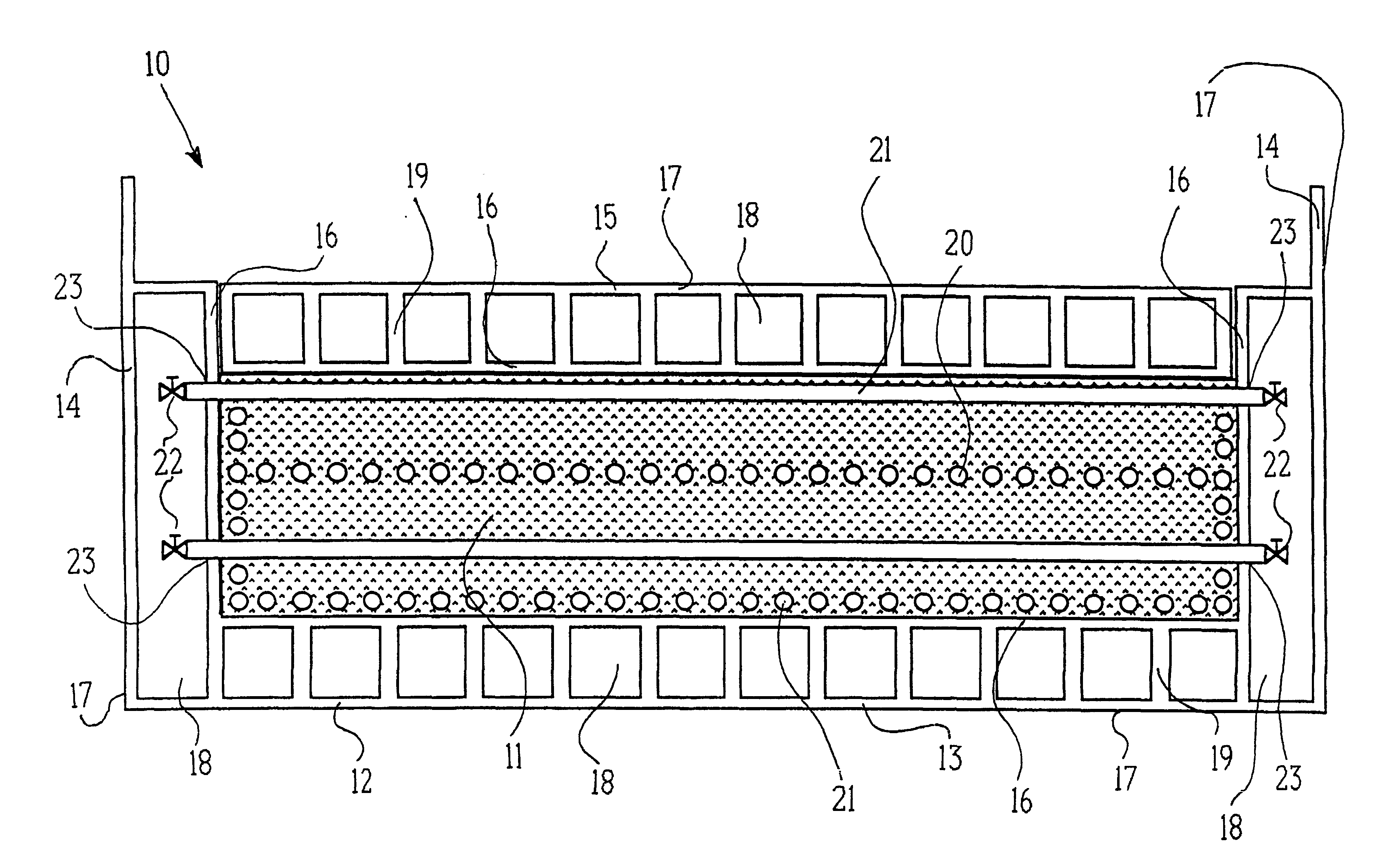
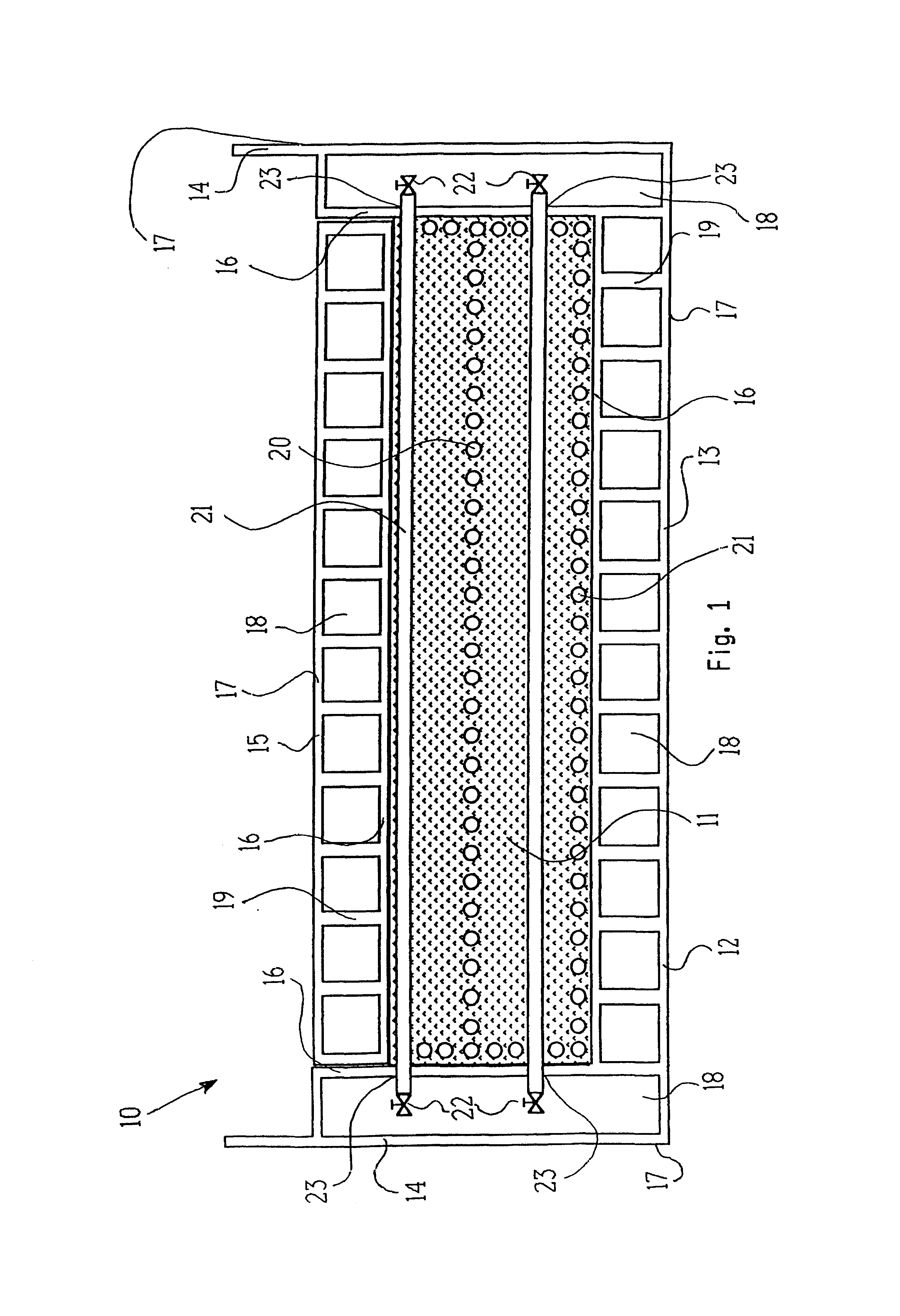
Referring to FIG. 1 there is indicated, generally at 10, in transverse section, an ice composite body according to the invention for use in the construction of fixed or floating structures located in or on water. The body 10 has an inner ice core 11, and a protective outer armour shell 12. The protective outer armour shell 12 is made from concrete material. The type of construction in concrete used is based on the method of construction of the hull of the tanker vessel "Selma" as described by Wig, Rudolph, American Society of Naval Architects, November, 1919, and referred to in detail by Turner, Colin W. R., Sea Breezes 1996, 936-944.

The protective outer armour shell 12 consists of a base section 13, side sections 14 and a separate top section 15. The top section 15 rests on the inner ice core 11 and is flee to move vertically between the side sections 14. The outer armour shell 12 has an inner wall 16 and an outer wall 17, defining a space 18 therebetween which acts as a means for ...


PUM


Abstract

An ice composite body (10) has an inner ice core (11) and a protective outer armour shell (12). The outer armour shell (12) consists of a base section (13), side sections (14) and a separate top section (15), which is free to move vertically between the side sections (14). The inner ice core (11) is maintained in a frozen condition in use by refrigeration pipes (21), which are located at various levels therethrough. The inner ice core (11) is built up from thin layers of ice which are frozen one after the other. Following the freezing of each layer of ice the layer is rolled using a roller apparatus which provides a roller pressure in the range of 3.5 to 8 Newtons / mm<2>. The ice composite body (10) can be used in warm or cool waters for applications such as bridges, breakwaters, causeways, pontoons, artificial islands, dams, tidal barrages, wave power barrages, harbour walls, wind power farms or aircraft runways.

Description

This invention relates to ice composite bodies for use in the construction of fixed or floating structures located in or on water. The invention also relates to a process for the construction of such ice composite bodies.Ice composite bodies can be used in warm or cool waters for applications such as bridges, breakwaters, causeways, pontoons, artificial islands, dams, tidal barrages, wave power barrages, harbour walls, wind power farms or aircraft runways.GB-A 2 071 295 discloses a method of producing a gravity ice platform, made in a floating flexible mould from a spray of ice flakes or chips, which are frozen in solid ice by using supercooled water, cold air or a freezing mixture. The resultant large blocks of ice can be used on their own or a number of the blocks may be joined together to form a desired structure. Because of the large volumes of ice involved these structures will sit stably on the waterbed and are capable of withstanding any forces to which they may be subjected,...

Claims


Application Information

Patent Timeline
Patent Type & Authority Patents(United States)
IPC IPC(8): B63B5/00B63B35/34E01D1/00E02B17/02E02B3/06E02D27/04E02D27/06E02B17/00F25C1/08
CPCB63B5/00B63B35/34E01D1/00E02B3/062E02B17/028E02D27/06B63B2231/64B63B2231/76F25C1/08Y02P60/85
Inventor MCALISTER, PADRAIG
Owner MCALISTER PADRAIG
Why Eureka
Try Eureka