Intelligent control to stabilize auto-ignition combustion without rapid pressure increase

a technology of intelligent control and auto-ignition combustion, applied in the direction of electrical control, machines/engines, output power, etc., can solve the problems of reducing the pressure around the top dead center during the compression process, unable to solve the problem of stabilizing auto-ignition combustion, and prolonging the combustion duration

Inactive Publication Date: 2004-04-13
NISSAN MOTOR CO LTD
View PDF9 Cites 22 Cited by
  • Summary
  • Abstract
  • Description
  • Claims
  • Application Information

AI Technical Summary

Benefits of technology

adjusting closing timing of the outlet control device in response to the monitored engine-surrounding environment indicative parameter, thereby to vary an exhaust gas retaining duration from the closing timing event of the outlet control device to opening timing event of the inlet control device when there is a change in the monitored engine-surrounding environment indicative parameter.
The inventors here have recognized that a change in engine-surrounding environment may cause a variation in pressure, temperature, and excess air ratio around top dead center during compression process, all of which, in turn, cause variation in ignition timing and combustion duration of auto-ignition combustion. An advantage of the above-mentioned preferred embodiment is that variation in ignition timing and combustion duration of auto-ignition combustion is prevented or at least suppressed to hold appropriate ignition timing and combustion duration against a change in engine-surrounding environment.
A change in engine-surrounding environment may cause a drop in pressure around top dead center during compression process. Such a drop in pressure causes auto-ignition at a delayed timing, resulting in prolonged combustion duration because of descending movement of a piston during the final stage of combustion. Such combustion is low in thermal efficiency and may induce misfire event. A change in engine-surrounding environment may cause a reduction of excess air around top dead center during compression process. With the same volumetric efficiency, a drop in density of air causes a reduction of excess air ratio around top dead center during compression process. Reduction in excess air ratio may cause rapid burning during combustion after auto-ignition or may cause auto-ignition at an early time prior to appropriate timing. Rapid burning and / or early ignition may cause knock event to occur, increasing, in level, combustion noise. Reduction in excess air ratio may cause an increase in amount of NOx emission. The second preferred embodiment contemplates adjusting closing timing of the inlet control device so as to vary the volumetric efficiency. An advantage of the second preferred embodiment is that variation in ignition timing and combustion duration of auto-ignition combustion is prevented or at least suppressed to hold appropriate ignition timing and combustion duration against a change in engine-surrounding environment by varying the volumetric efficiency.
adjusting closing timing of the outlet control device in response to the monitored engine operating temperature, thereby to vary an exhaust gas retaining duration from the closing timing event of the outlet control device to opening timing event of the inlet control device when there is a change in the monitored engine operating temperature.
A change in engine operating temperature as represented by an engine oil temperature or an engine coolant temperature may cause a variation in temperature, and excess air ratio around top dead center during compression process, all of which, in turn, cause variation in ignition timing and combustion duration of auto-ignition combustion. A variation of in-cylinder temperature may cause a variation in mass of intake air inhaled per one cycle with the volumetric efficiency held the same. An advantage of the third preferred embodiment is that variation in ignition timing and combustion duration of auto-ignition combustion is prevented or at least suppressed to hold appropriate ignition timing and combustion duration by varying an exhaust gas retaining duration to vary in-cylinder temperature during the next cycle when there is a change in engine operating temperature. During the early stages of a cold start of an engine, the engine operating temperature inhibits build-up of appropriate temperature and excess air ratio around top dead center during compression process, making it difficult to achieve stable auto-ignition combustion. The third preferred embodiment of the present invention contemplates varying exhaust gas retaining duration to retain appropriate amount of exhaust gas needed to raise in-cylinder temperature for proper combustion in the next engine cycle.

Problems solved by technology

However, JP-A 10-266878 does not contemplate a solution to stabilizing auto-ignition combustion without rapid increase of in-cylinder pressure against a change other than a change in load request.
A change in engine-surrounding environment may cause a drop in pressure around top dead center during compression process.
Such a drop in pressure causes auto-ignition at a delayed timing, resulting in prolonged combustion duration because of descending movement of a piston during the final stage of combustion.
Such combustion is low in thermal efficiency and may induce misfire event.
Reduction in excess air ratio may cause rapid burning during combustion after auto-ignition or may cause auto-ignition at an early time prior to appropriate timing.
Rapid burning and / or early ignition may cause knock event to occur, increasing, in level, combustion noise.
Reduction in excess air ratio may cause an increase in amount of NOx emission.
During the early stages of a cold start of an engine, the engine operating temperature inhibits build-up of appropriate temperature and excess air ratio around top dead center during compression process, making it difficult to achieve stable auto-ignition combustion.
During operation of an engine over the number of engine cycles with bad combustion stability, the cycle-by-cycle variation in combustion termination is considerably great, so the cycle-by-cycle variation in temperature of the retained exhaust gas during exhaust gas retaining duration is inevitably great.
Further, the density of unburnt fuel within the retained exhaust gas per one cycle may differ considerably from that per one of the subsequent cycles during engine operation with bad combustion stability.

Method used


Image

  • Intelligent control to stabilize auto-ignition combustion without rapid pressure increase
  • Intelligent control to stabilize auto-ignition combustion without rapid pressure increase
  • Intelligent control to stabilize auto-ignition combustion without rapid pressure increase

Examples


Embodiment Construction

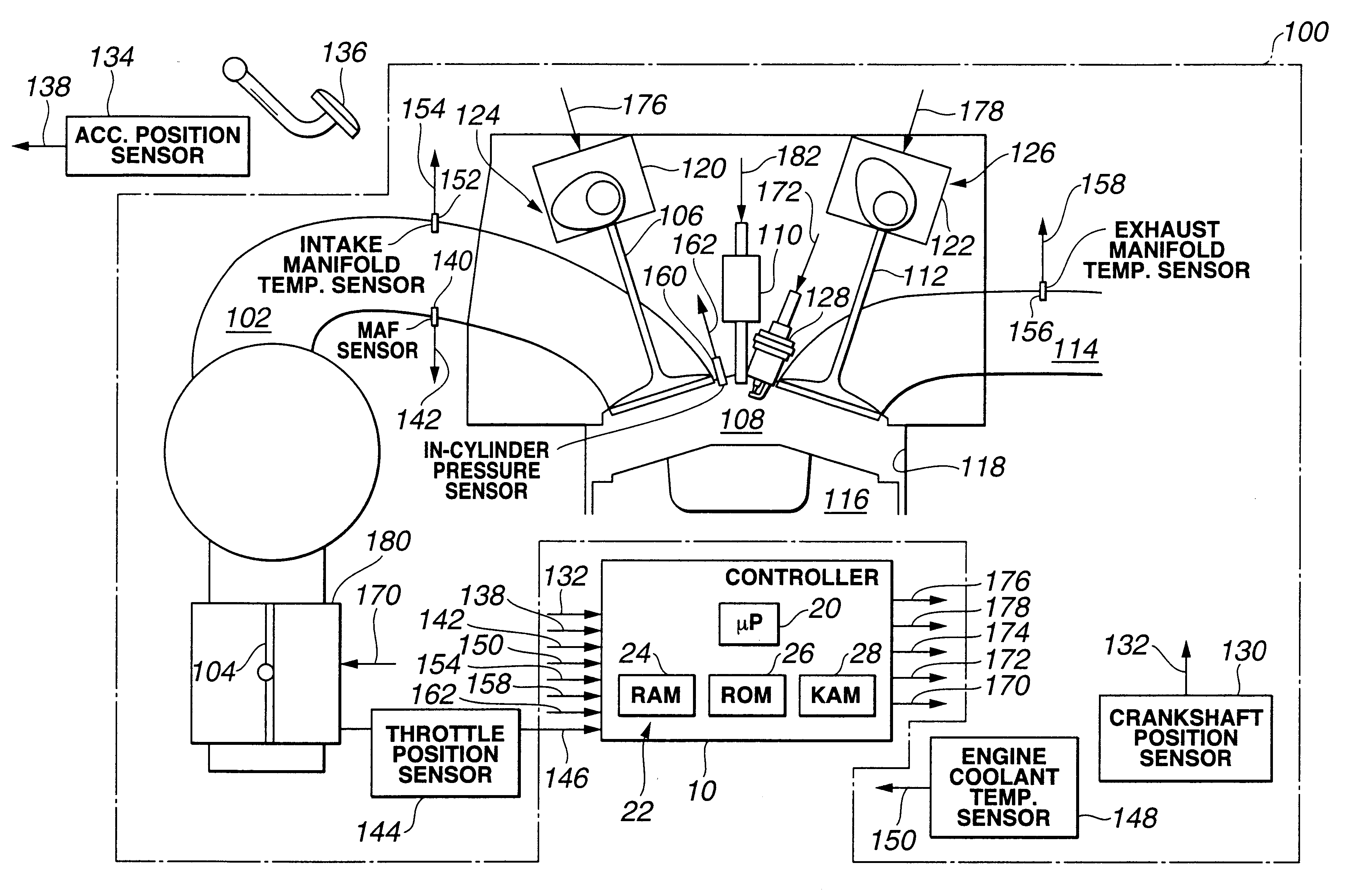
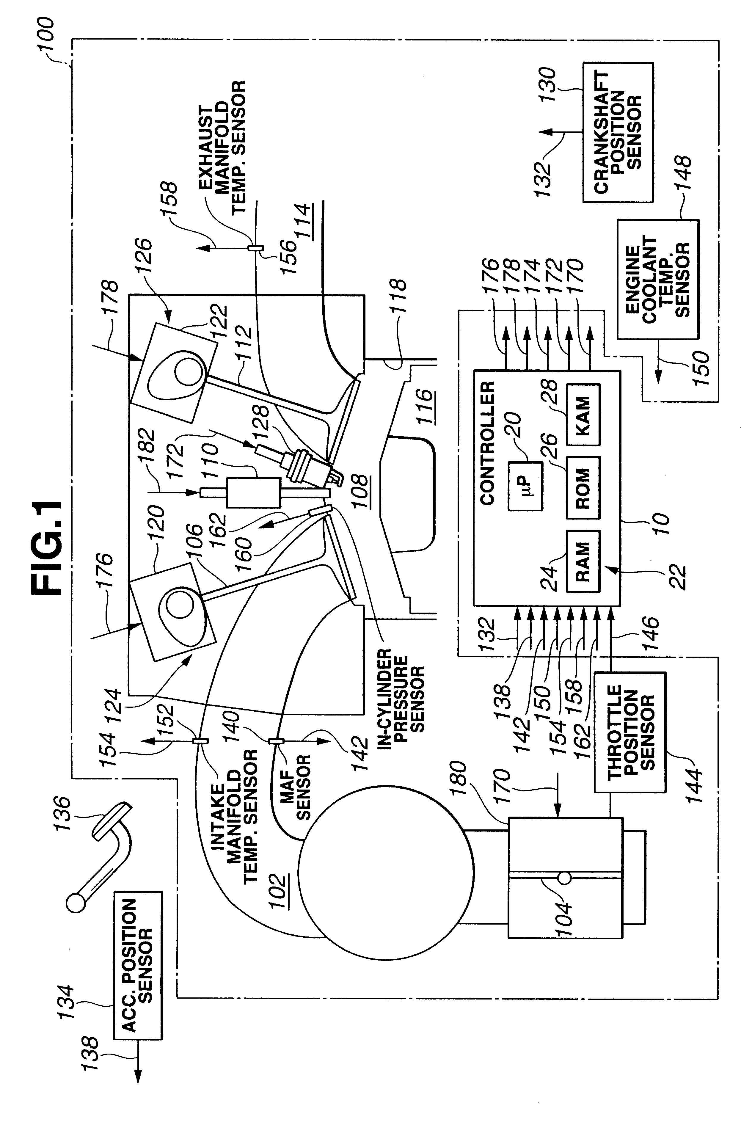
FIG. 1 shows an electronic engine controller (ECC) 10 and an internal combustion engine 100, which comprises a plurality of cylinders, one of which is shown in FIG. 1. Engine 100 draws an intake air charge through intake manifold 102 past a throttle plate 104, and intake valve 106 and into combustion chamber 108. An air / fuel mixture, which consists of the air charge and fuel injected by fuel injector 110 of a fuel injection device, is ignited in combustion chamber 108, and exhaust gas resulting from combustion of the air / fuel mixture is transported past exhaust valve 112 through exhaust manifold 114. A piston 116 is coupled to a crankshaft, not shown, and moves in a linear fashion within a cylinder defined by cylinder walls 118.

Valve controllers 120 and 122 are provided to actuate intake and exhaust valves 106 and 112. In a preferred embodiment, intake valve 106 and valve controller 120 constitute an inlet control device 124 for controlling flow of intake air into combustion chamber...


PUM


Abstract

The present invention concerns a method and a system for operating an internal combustion engine capable of performing auto-ignition combustion as well as spark-ignition combustion. In auto-ignition combustion mode, inlet and outlet control devices are adjusted to retain a portion of exhaust gas for subjecting the retained exhaust gas to compression. In one preferred embodiment, a parameter indicative of engine-surrounding environment is monitored. Closing timing of the outlet control device is adjusted in response to the monitored parameter, thereby to vary an exhaust gas retaining duration when there is a change in the monitored parameter.

Description

1. Field of the InventionThe present invention relates to the field of engine control to induce auto-ignition combustion of fuel including gasoline, and more particularly to the field of stabilizing auto-ignition combustion without rapid increase of in-cylinder pressure.2. Description of Related ArtAccording to JP-A 10-266878, it is known to vary an exhaust gas retaining duration to accomplish auto-ignition combustion of gasoline fuel over varying load request from low to middle level. Exhaust gas retaining duration extends from closure (or closing timing) of exhaust valve to opening (or opening timing) of intake valve. To meet decreasing load request, closure of exhaust valve is moved to increase the amount of advance from top dead center during exhaust or induction process, thereby to increase remaining exhaust gas content to decrease in quantity fresh intake air. Besides, opening of intake valve is moved to increase the amount of delay from top dead center during exhaust or induc...

Claims


Application Information

Patent Timeline
Patent Type & Authority Patents(United States)
IPC IPC(8): F02D41/14F02D41/40F02D41/30F02D13/02F02B75/00F02B23/10F02B1/12F02B75/12F02B1/00F02M25/07F02D41/02F02D41/04F02D41/38F02D43/00F02D45/00
CPCF02D13/0219F02D13/0265F02D35/024F02D35/026F02D41/006F02D41/1497F02D41/3035F02D41/402F02M25/0752F02B1/12F02B23/101F02B2075/125F02D41/187F02D2041/001F02D2200/0406F02D2200/0414Y02T10/18Y02T10/44Y02T10/123Y02T10/47F02M26/01Y02T10/12Y02T10/40
Inventor KAKUHO, AKIHIKOMIYAKUBO, HIROSHI
Owner NISSAN MOTOR CO LTD
Why Eureka
Try Eureka