Base station apparatus and radio communication method

a technology for radio communication and base stations, applied in the direction of transmission monitoring, electromagnetic wave modulation, power management, etc., can solve the problems of discontinuation or overlap of transmission signals, delay may be a major factor of general deterioration of communication quality

Inactive Publication Date: 2004-04-13
INTERTECH GLOBAL LLC
View PDF17 Cites 19 Cited by
  • Summary
  • Abstract
  • Description
  • Claims
  • Application Information

AI Technical Summary

Problems solved by technology

Such a propagation path is called a "multi-path propagation path" and communication quality generally deteriorates if this multi-path propagation cannot be compensated.
Thus, if this signal contains a great delay, this delay may be a major factor of deterioration of the communication quality.
This is because in the case of continuous transmission, changing transmission timing will cause problems such as discontinuation or overlap of a transmission signal and collapse of orthogonality (code orthogonality in the case of CDMA, and time orthogonality in the case of TDMA) with other channels with which the transmission signal is multiplexed. etc.
However, when the switching of transmission directivities is controlled according to the conventional system described above, if transmission is performed by selecting a path with a widely different propagation delay, the rece...

Method used


Image

  • Base station apparatus and radio communication method
  • Base station apparatus and radio communication method
  • Base station apparatus and radio communication method

Examples


embodiment 1

FIG. 7 is a block diagram showing a configuration of a base station according to Embodiment 1 of the present invention. FIG. 8 is a block diagram showing a configuration of a terminal according to Embodiment 1 of the present invention. FIG. 7 describes only the transmitting side. Here, a CDMA system using a spread spectrum (SS) communication system is assumed.

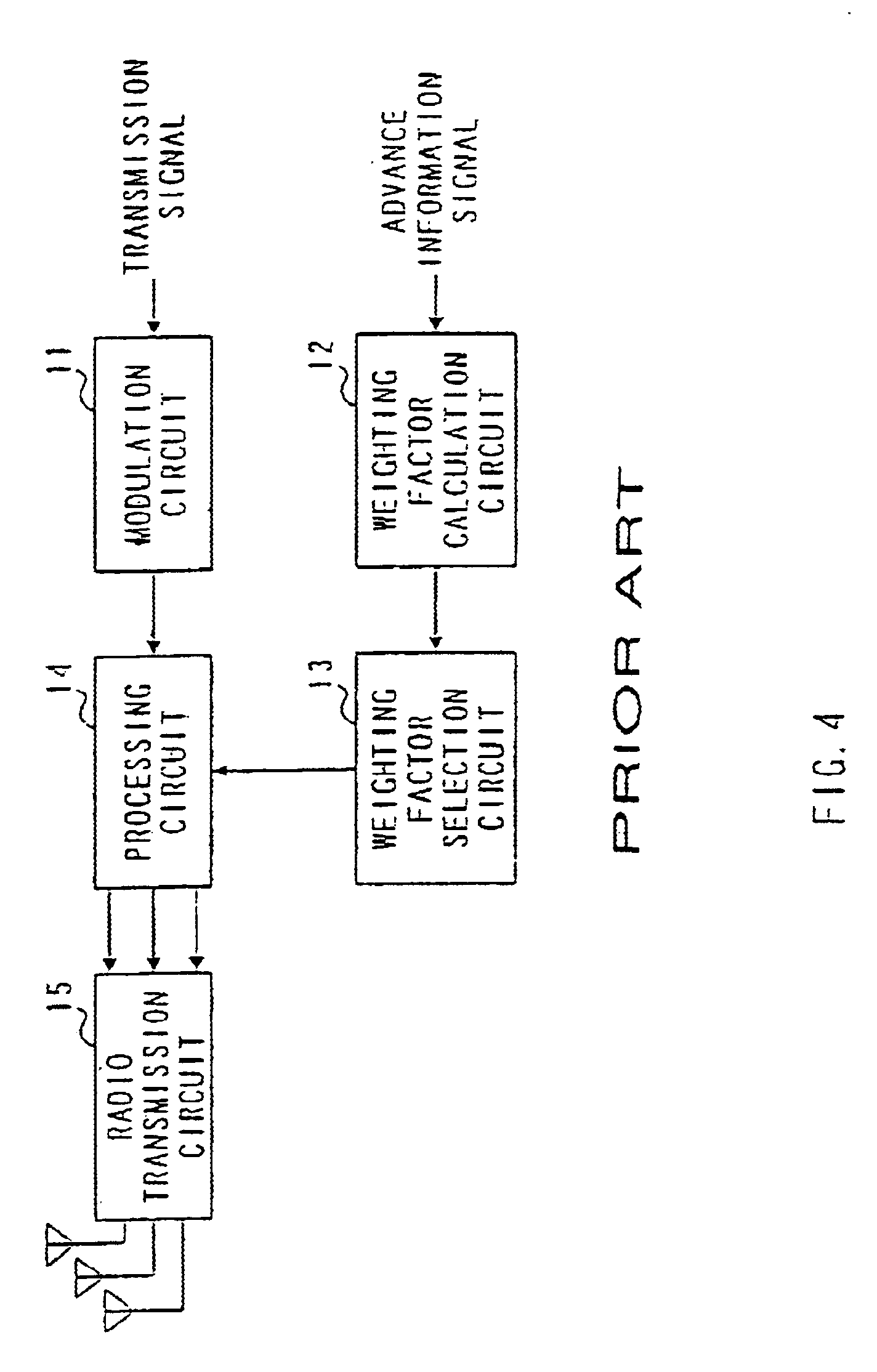
First, the calculation of the base station shown in FIG. 7 is explained. By way of example, suppose the number of antennas is 3. A transmission signal is modulated by modulation circuit 101. On the other hand, of a plurality of transmission weighting factors calculated by weighting factor calculation circuit 102 based on an advance information signal such as PHO shift, the most suitable one or two weighting factors are selected by weighting factor selection circuit 103 and multiplied by processing circuits 104 and 105. These transmission signals are then combined (multiplexed) by combination circuit 106, frequency-converted and...

embodiment 2

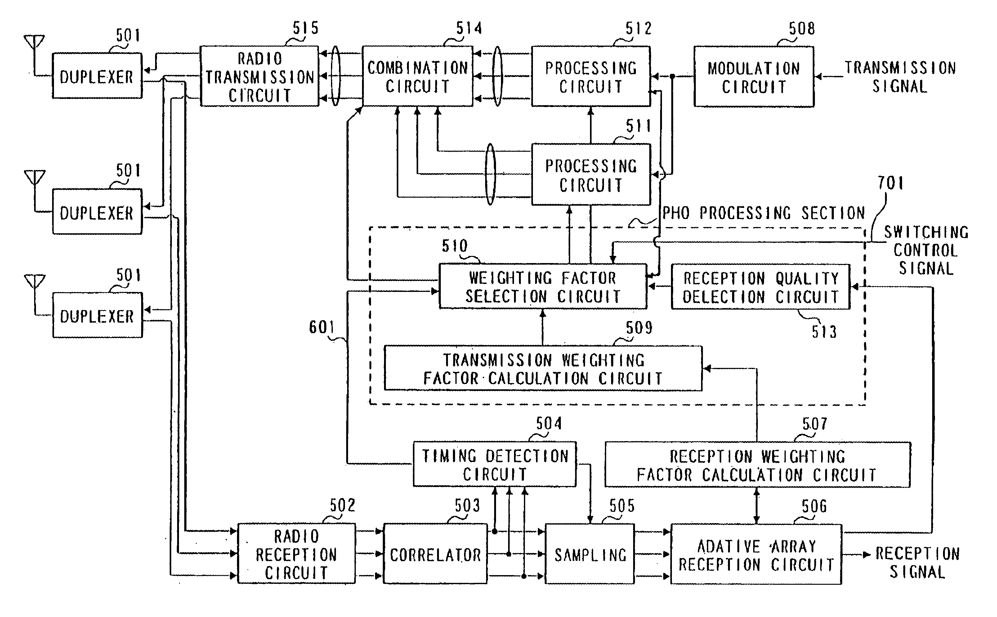
FIG. 11 is a block diagram showing a configuration of a base station according to Embodiment 2 of the present invention. The present embodiment assumes a CDMA system using a spread spectrum (SS) communication system. Embodiment 2 is explained using a base station to which adaptive array transmission based on adaptive array reception and its information is applied and the terminal at the other end of communication shown in FIG. 8. By way of example, suppose the number of antennas in the base station is 3.

First, the uplink is explained. The terminal on its transmitting side modulates a transmission signal by modulation circuit 207. This modulated signal is frequency-converted and amplified by radio transmission circuit 208 and transmitted from the antenna via antenna duplexer 201.

The base station sends signals received from the antennas to radio reception circuit 502 via antenna duplexers 501. Radio reception circuit 502 carries out amplification, frequency conversion and A / D conversi...

embodiment 3

The present embodiment describes a case where PHO is applied to a TDMA transmission system. A radio communication apparatus in this case has basically the same configuration as that of the base station shown in FIG. 7. It is different from the base station shown in FIG. 7 in that it has a different combination circuit.

A TDMA transmission system performs transmission in a time slot configuration as shown in FIG. 15. In the TDMA transmission system, it is desirable to suppress multi-path propagation by transmitting signals to either path A or path B. In this case, each signal is transmitted using a separate slot.

The combination circuit in this case contains transmission level control circuit 1003 as shown in FIG. 16 that individually controls the transmission level of each signal subjected to a product sum calculation. In this configuration, a signal subjected to a product sum calculation is multiplied by coefficients by multiplication sections 1001 and 1002, respectively. Then, signa...


PUM


Abstract

When switching to a path whose directivity changes greatly or a path with a widely different propagation delay, transmission is performed for both directivities for a certain period of time. Then, transmission is performed for one directivity. When the switching of transmission directivities is controlled, this allows correct reception of signals and prevents instantaneous interruption due to loss of synchronism even if transmission is performed by switching to a path with a widely different propagation delay.

Description

1. Field of the InventionThe present invention relates to a base station apparatus and radio communication method used in a digital radio communication system.2. Description of the Related ArtA propagation model in a radio communication is explained with reference to FIG. 1. By way of example, suppose the number of antennas of the radio communication apparatus (base station apparatus) is 3. In FIG. 1, two paths A and B indicate downlink (transmission from a base station to terminal) propagation paths. A signal transmitted from base station apparatus 1 is reflected by building 2 and arrives at an antenna of terminal apparatus 3. Such a propagation path is called a "multi-path propagation path" and communication quality generally deteriorates if this multi-path propagation cannot be compensated. In this example, suppose the signal from building 2 is received by the receiving side with a delay within the range of its time resolution. Transmission directivity in this case is shown in FI...

Claims


Application Information

Patent Timeline
IPC IPC(8): H04B7/005H04B7/04H04B7/06H01Q3/26H04B1/7113H04B7/10H04B7/155H04J13/00
CPCH04B7/0615H04W52/42H04B7/02H04B7/155H04W88/08
Inventor MIYA, KAZUYUKIHIRAMATSU, KATSUHIKOTAKAHASHI, HIDEYUKI
Owner INTERTECH GLOBAL LLC
Why Eureka
Try Eureka