Systems and methods for facilitating testing of pad drivers of integrated circuits

a technology of integrated circuits and pad drivers, which is applied in the field of integrated circuits, can solve the problems of imposing other testing restrictions, limiting the number of ic pins (or pads) that can be tested by a particular ate, and oftentimes being cost prohibitive to provide an ate with an appropriately high pin count and/or an appropriately high operating frequency in order to eliminate the aforementioned deficiencies

Inactive Publication Date: 2004-04-13
AVAGO TECH WIRELESS IP SINGAPORE PTE
View PDF13 Cites 28 Cited by
  • Summary
  • Abstract
  • Description
  • Claims
  • Application Information

AI Technical Summary

Problems solved by technology

A practical limitation to the utilization of ATE for testing IC's, however, is that the number of IC pins (or pads) that can be tested by a particular ATE has, heretofore, been limited by the physical configuration of the ATE.
Additionally, performance limitations of a particular ATE may impose certain other testing restrictions.
Although configuring an ATE with additional test channels and / or a higher operating frequency may be accomplished, providing an ATE with an appropriately high pin count and / or an appropriately high operating frequency in order to eliminate the aforementioned deficiencies is, oftentimes, cost prohibitive.
As should be readily apparent, many of these "stop-gap" testing procedures may result in a loss of test coverage and, thereby, may lead to an increase in numbers of defective IC devices being shipped.
Moreover, the practice of limiting, through design implementation, the pin count and / or frequency of the IC device to accommodate existing ATE is, oftentimes, an unacceptable constraint on IC design.
Digital self-test circuitry, however, is largely unable to remedy the foregoing and / or other deficiencies.

Method used


Image

  • Systems and methods for facilitating testing of pad drivers of integrated circuits
  • Systems and methods for facilitating testing of pad drivers of integrated circuits
  • Systems and methods for facilitating testing of pad drivers of integrated circuits

Examples


Embodiment Construction

Reference will now be made in detail to the description of the invention as illustrated in the drawings with like numerals indicating like parts throughout the several views.

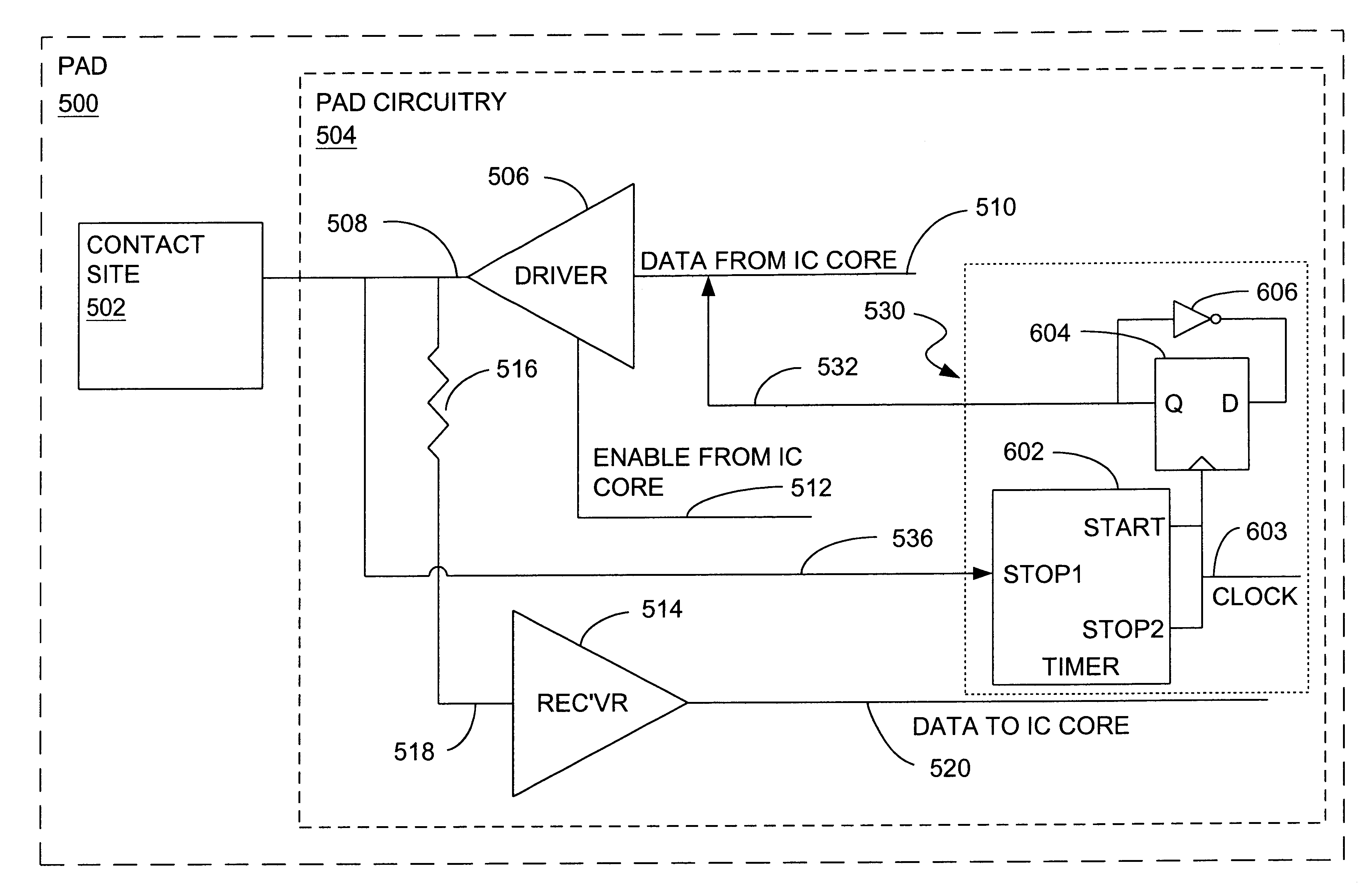
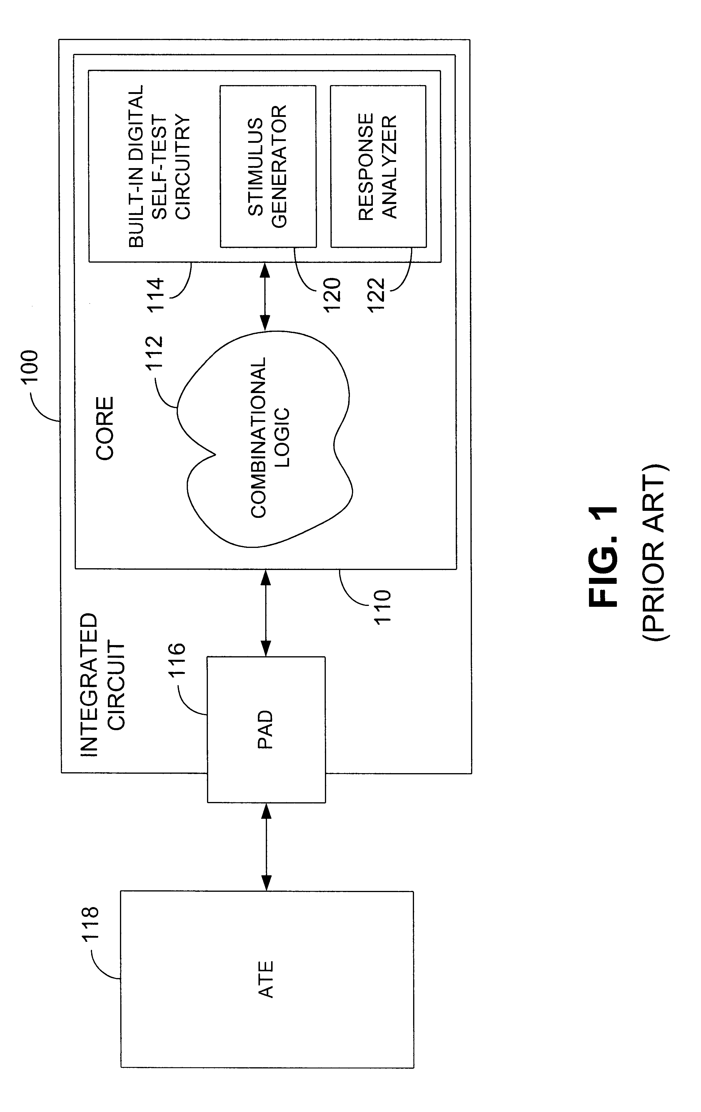
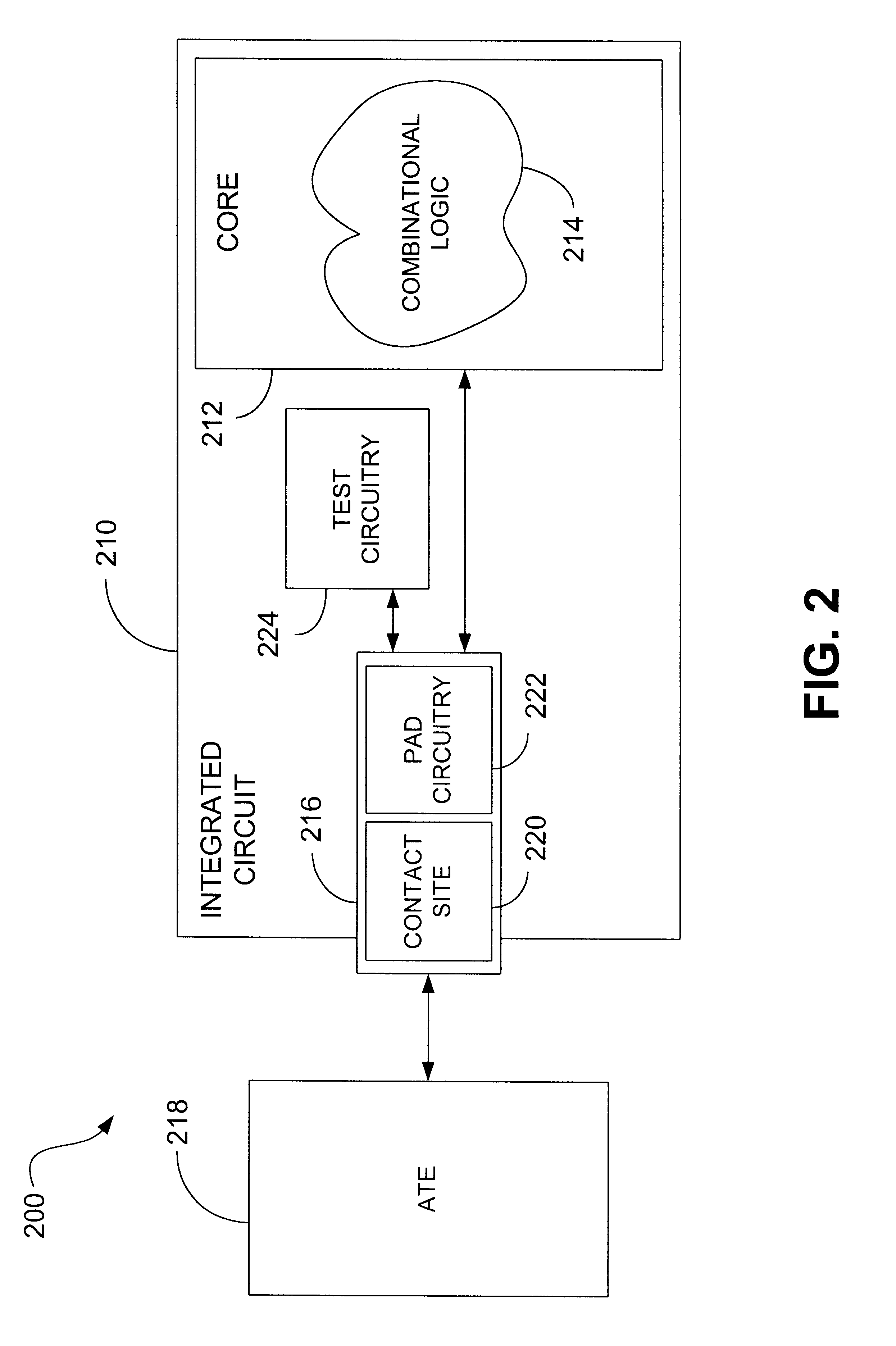
Utilizing the digital self-test circuitry of FIG. 1 as a point of comparison, general characteristics of a preferred embodiment of the test system of the present invention will now be described in reference to the schematic diagram of FIG. 2. As depicted in FIG. 2, test system 200 incorporates an integrated circuit 210 which includes a core 212. Core 212 incorporates logic 214 and electrically communicates with a pad 216, which is configured to allow intercommunication of the logic with devices, such as ATE 218, for example, external to the integrated circuit. As mentioned hereinbefore, a pad, such as pad 216, includes a physical or contact site 220, which serves as an electrical contact for IC 210, as well as pad circuitry 222, which cooperates with the contact site to enable electrical communication between co...


PUM

PropertyMeasurementUnit
driver clock-to-q timeaaaaaaaaaa
driver clock-to-g timeaaaaaaaaaa
receiver setup timeaaaaaaaaaa

Abstract

A preferred integrated circuit (IC) includes a first pad electrically communicating with at least a portion of the IC. The first pad includes a first driver and a first receiver, with the first driver being configured to provide a first pad output signal to a component external to the IC, and the first receiver being configured to receive a first pad input signal from a component external to the IC. The first receiver also is configured to provide, to a component internal to the IC, a first receiver digital output signal in response to the first pad input signal. A first test circuit also is provided that is internal to the IC. The first test circuit is adapted to provide information corresponding to the driver clock-to-q time of the first pad. Systems, methods and computer-readable media also are provided.

Description

1. Field of the InventionThe present invention generally relates to integrated circuits and, in particular, to systems and methods for facilitating, within an integrated circuit, driver clock-to-output delay testing of pads of the integrated circuit.2. Description of the Related ArtHeretofore, integrated circuit (IC) devices have been tested and verified using a variety of test methods. For example, IC devices have been tested and verified to be defect-free using functional test vectors, such as those applied to the IC by the use of automated test equipment (ATE), which stimulate and verify the IC device functionality at the pin level of the device. A practical limitation to the utilization of ATE for testing IC's, however, is that the number of IC pins (or pads) that can be tested by a particular ATE has, heretofore, been limited by the physical configuration of the ATE. For instance, the number of pads of the IC to be tested may exceed the number of test channels provided by an AT...

Claims


Application Information

Patent Timeline
Patent Type & Authority Patents(United States)
IPC IPC(8): G01R31/3187G01R31/28G01R31/319G06F11/24H01L21/822H01L27/04
CPCG01R31/3187G01R31/31922G01R31/31926G06F11/24
Inventor REARICK, JEFFROHRBAUGH, JOHNSHEPSTON, SHAD
Owner AVAGO TECH WIRELESS IP SINGAPORE PTE
Why Eureka
Try Eureka