Support for sustaining and/or forming a dental prosthesis

a technology for supporting and/or forming dental prostheses, applied in dental prostheses, medical science, dentistry, etc., can solve the problems of small rotational or swiveling movements of the cap relative to the support, inability to design a cap, and inability to support the patien

Inactive Publication Date: 2004-04-27
STRAUMANN HLDG AG +1
View PDF28 Cites 101 Cited by
  • Summary
  • Abstract
  • Description
  • Claims
  • Application Information

AI Technical Summary

Benefits of technology

The goal of the invention is to avoid the disadvantages of the known supports and of a device formed therefrom, as well as a superstructure and/or impression element and/or a healing element. In particular the opportunity is to be offered for an element with a cap to be normally positioned stably on the support in a rotational position defined as accurately as possible so that the cap, even with high forces acting on it approximately transversely to one axis of the support and/or torsional stresses, rem

Problems solved by technology

If large forces act on the cap approximately perpendicularly to the axis and bring about shear forces or torsional forces between the cap and the support, there is the danger that the cap will execute small rotational or swiveling movements relative to the support.
Such tiny rotational movements may cause the dental treatment to fail.
Sometimes, however, it is advantageous for the cap to be placed on the support in only a single rotational position, which is not possible with the known support.
In this known head, it would also be practically impossible to design a cap so that it abuts both the flat surfaces of the octagonal section and the conical section of the head.
Since the octagonal section has only a relatively small axial dimension, the cap receives little support with respect to laterally acting forces, i.e. forces transverse to the axis, impairing the stability of the connection of the cap or the superstructure element to the additional support.
This support has the disadvantage however that the spacing sleeve is guided laterally only in a short cylindrical guide area of the hole having a relatively small diameter below the grooves and is supported against the forces directed approximately transversely at the implant axis.
In combination with the small dimensions of the guide area, this results in a high risk of the dental prosthesis executing

Method used


Image

  • Support for sustaining and/or forming a dental prosthesis
  • Support for sustaining and/or forming a dental prosthesis
  • Support for sustaining and/or forming a dental prosthesis

Examples


Embodiment Construction

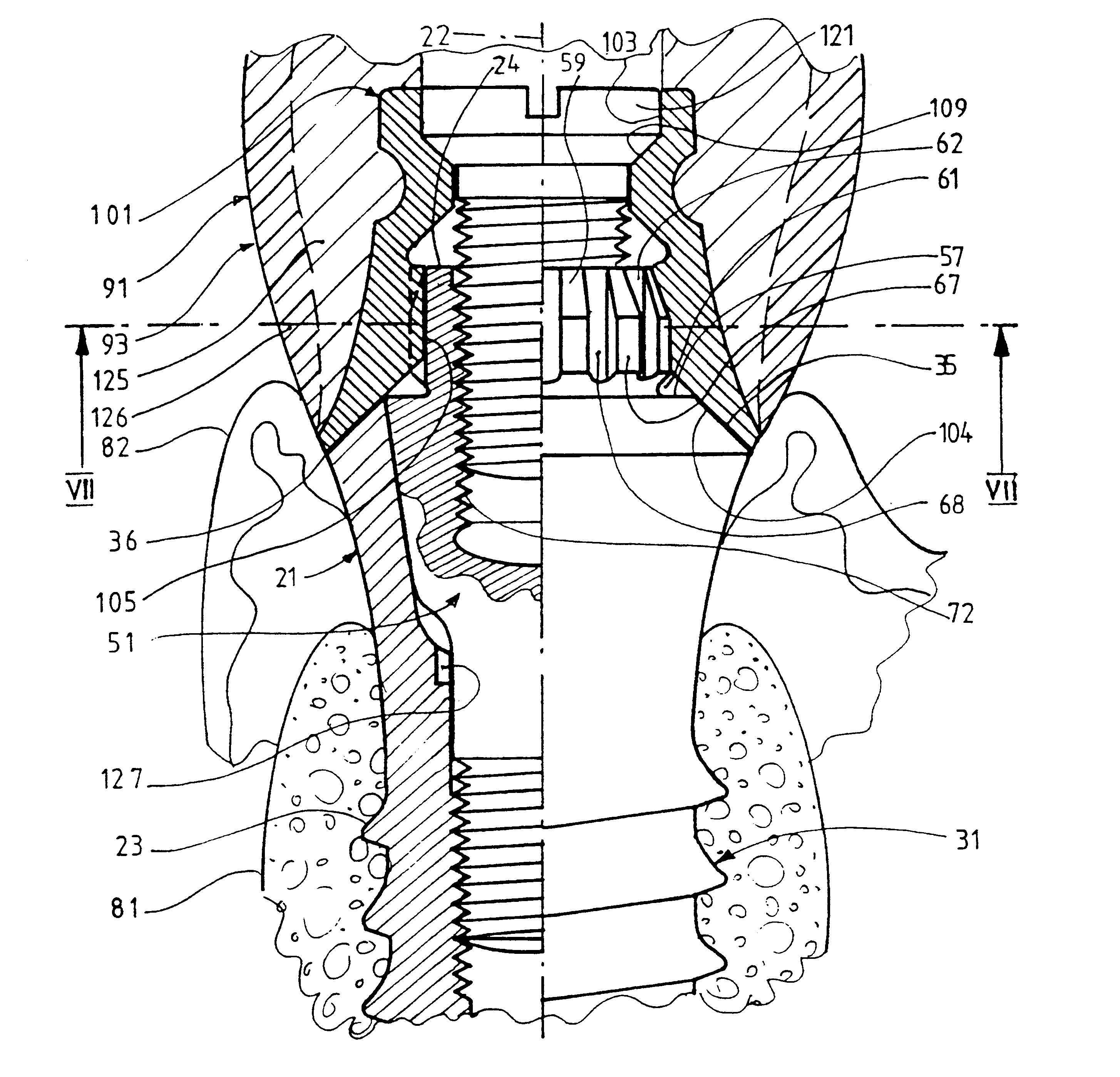
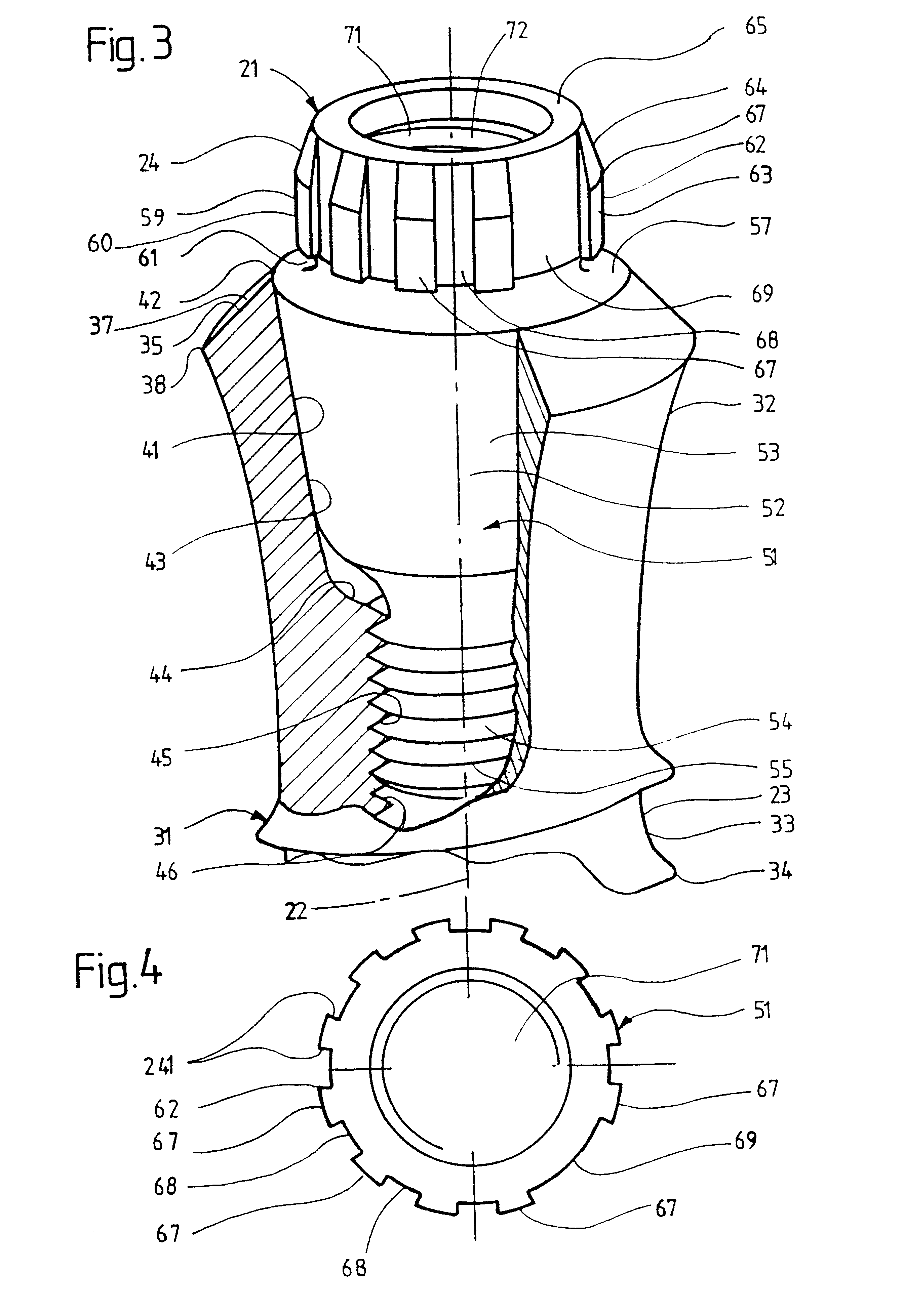
The support 21 shown in FIG. 3 is generally rotationally symmetrical about an axis 22 and at the bottom has an anchoring part 23 intended for anchoring in a bone of an upper or lower jaw and a head part 24 for projecting out of the bone. Support 21 has two originally separate elongate one-piece metal parts, namely an implant 31 and a secondary part 51 removably attachable thereto.

Implant 31 has an upper end section 32 that tapers downward. It is abutted at the bottom by a generally cylindrical section 33 which is provided for example with an external thread 34 and forms at least the largest part of anchoring part 23 of the support. The lower end of section 33, not visible in FIG. 3, forms the first free end of the total support. Implant 31 has an implant shoulder 35 at the upper end. This shoulder has an annular conical flat shoulder surface 37 that fully surrounds the axis and tapers upward away from the anchoring part. Head part 24 in axial projection is enclosed by at least the o...


PUM


Abstract

A support for sustaining and/or forming a dental prosthesis, comprises an axle, an anchoring part which can be anchored in a bone or a master model, and a head part which protrudes out of said bone or master mode. The head part has intermediate spaces distributed around the axis, i.e., several first intermediate spaces forming a divided circle, and a second, wider and/or deeper intermediate space. A cap can be fixed to the support. The cap has at least one projecting part for engaging in an intermediate space and, optionally, can be configured for fixing in several different rotational positions or a single rotational position, the support allowing exact positioning. The cap can also be produced without a projecting part of the type mentioned. The same support can be used to form different types of dental prostheses.

Description

TECHNICAL AREAThe invention relates to a support for holding and / or forming a dental prosthesis with an axis, an anchoring part for anchoring in a bone of the lower or upper jaw of a patient and / or in a master model and a head part intended to project from the bone and / or master model. This head part serves to support an originally separate element attachable to the support with a cap. The cap can for example be a part of a dental prosthesis such as an individual artificial tooth or a bridge or a prosthesis having several teeth. The possibility also exists however of first attaching a so-called burnout cap made of plastic to the support. The burnout cap can serve for making a casting model and a casting impression, then be burned off from the latter and replaced by a impression cap when the cast impression is used.PRIOR ARTFor certain applications, it should be possible to attach the cap in a specific rotational position on the support. A support known from EP 0 685 208 A has an imp...

Claims


Application Information

Patent Timeline
IPC IPC(8): A61C8/00A61C13/12
CPCA61C8/0001A61C8/0022A61C8/005A61C8/0066A61C8/0069A61C8/008A61C8/0054A61C8/006
Inventor SUTTER, FRANZ
Owner STRAUMANN HLDG AG
Why Eureka
Try Eureka