
Tufted pile structure having binder concentrated beneath the backstitches

a pile structure and backstitched technology, applied in weaving, pattern making, transportation and packaging, etc., can solve the problems of increasing the weight of carpets, and increasing the amount of binder was

Inactive Publication Date: 2004-04-27
INVISTA NORTH AMERICA R L
View PDF73 Cites 26 Cited by
  • Summary
  • Abstract
  • Description
  • Claims
  • Application Information

AI Technical Summary

Benefits of technology

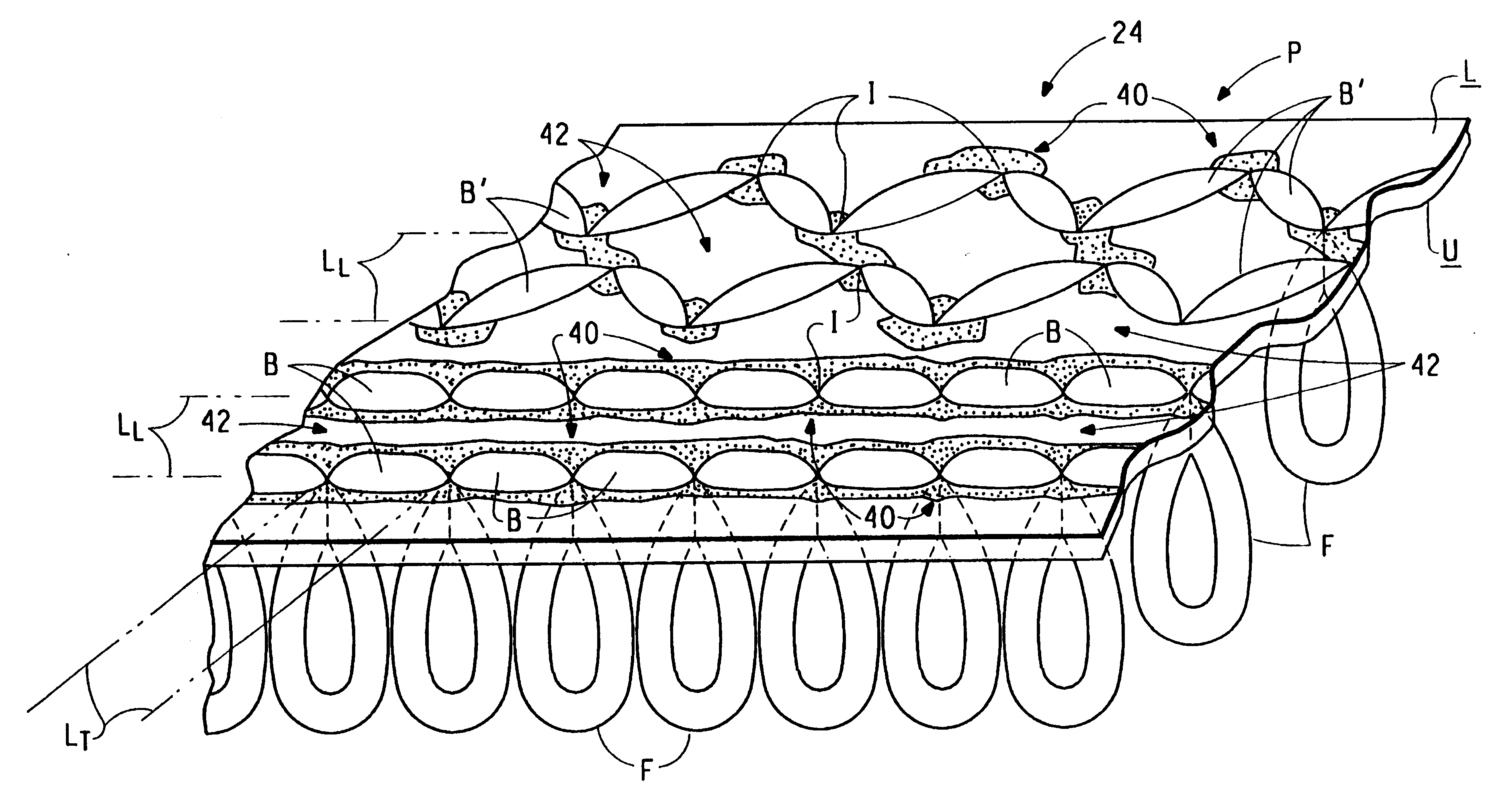
"The present invention relates to a method of manufacturing a tufted pile surface structure that concentrates binder material beneath the backstitch elements to produce a lighter and more flexible carpet structure. The technical effect of this invention is to provide a method that reduces binder material wastage, stiffens the carpet, and increases carpet weight. The binder material is applied before tufting and is activated during the tufting process to hold the backstitch elements in place. The binder material is concentrated along the insertion points, with the lower face of the backing being left substantially free of binder. The invention also provides a tufting system and a heat finishing apparatus for producing the tufted pile surface structure."

Problems solved by technology

In actuality, only a small portion of the binder material serves to hold the backstitch elements in place, while a large portion of the binder material is wasted.
Using very large quantities of binder to achieve deeper penetration of the binder through the backing to improve pull-out or unraveling resistance increases binder wastage, stiffens the carpet, and increases carpet weight.

Method used


Image

  • Tufted pile structure having binder concentrated beneath the backstitches
  • Tufted pile structure having binder concentrated beneath the backstitches
  • Tufted pile structure having binder concentrated beneath the backstitches

Examples


Embodiment Construction

Throughout the following detailed description similar reference numerals refer to similar elements in all figures of the drawings.

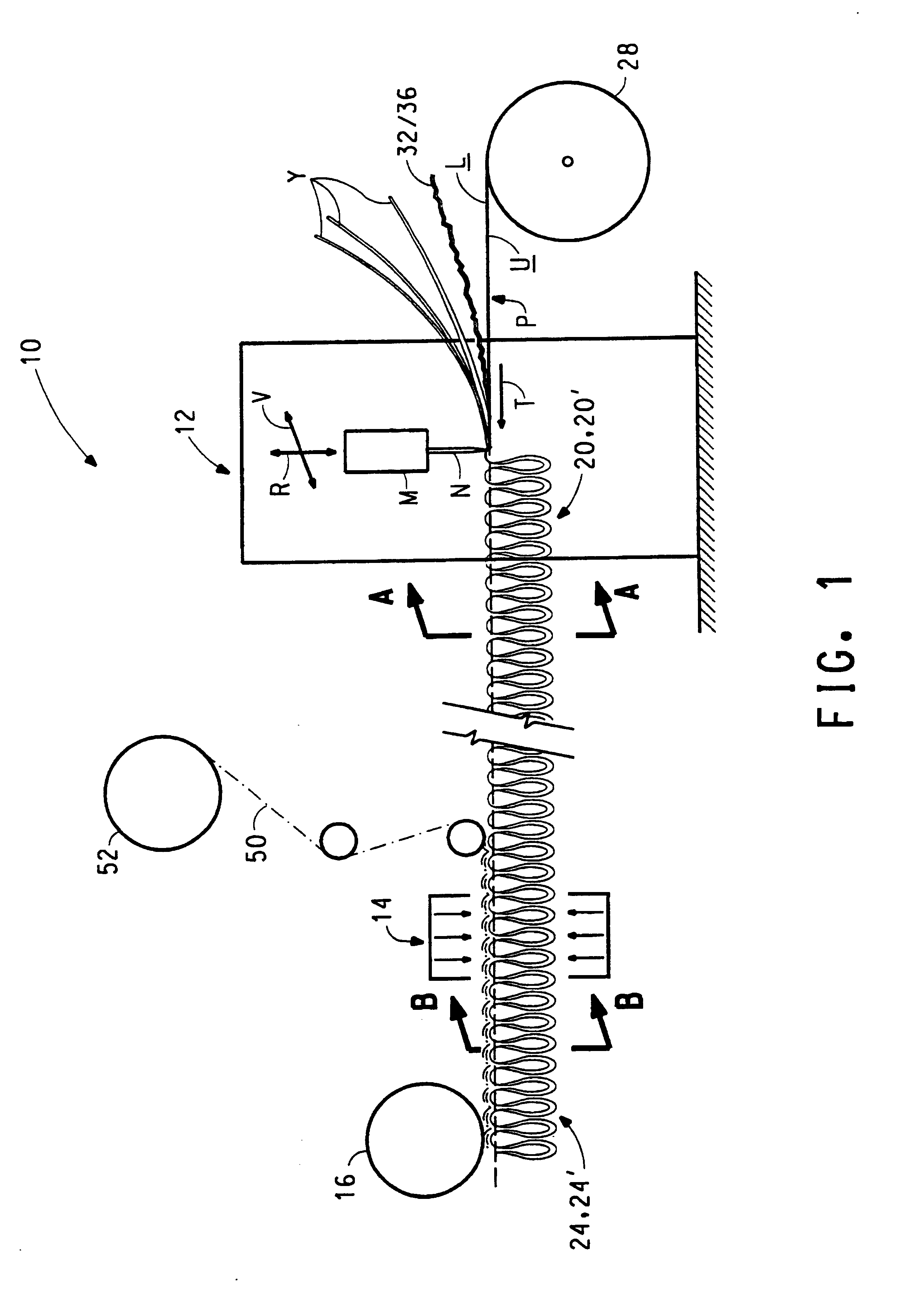
FIG. 1 is a diagrammatic illustration of an overall system 10 for producing and finishing a tufted pile surface structure in accordance with the present invention. The system 10 includes a tufting apparatus generally indicated by the reference character 12 followed by a heat finishing apparatus generally indicated by the reference character 14. The tufting apparatus 12 and the heat finishing apparatus 14 may be physically disposed in the same housing, if desired. Downstream of the heat finishing apparatus 14 is a compression roller 16. The temperature of the roller 16 is typically kept at room temperature.

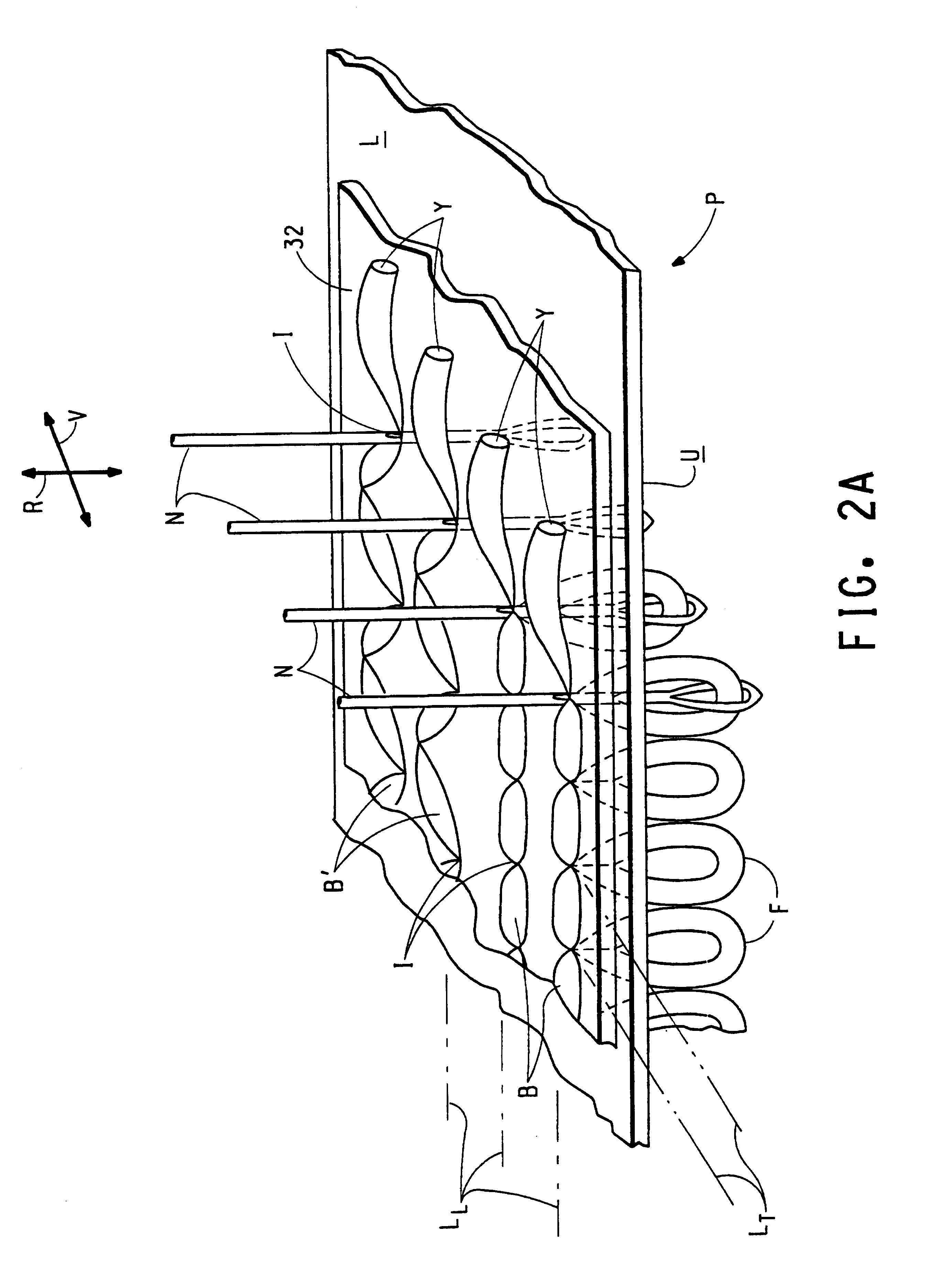
The tufting apparatus 12 produces a tufted pile surface structure generally indicated by the reference character 20, 20' in accordance with the alternate embodiments of the present invention. The pile surface structure 20 is illustrated herein in FIG. 2A...


PUM

PropertyMeasurementUnit
structureaaaaaaaaaa
pile surface structureaaaaaaaaaa
surface structureaaaaaaaaaa

Abstract

A concentrate of binder at the tufts produces a lighter and more flexible carpet, which allows for direct attachment of hook-and-loop means on the carpet backing. Thermoplastic binder yarns are pinned by the pile yarns against the primary backing. Subsequent application of heat melts the binder yarns and fuses the tufts and primary backing together. An alternate embodiment uses highly shrinkable binder sheet placed over the backing before tufting, instead of the binder yarns.

Description

1. Field of the InventionThe present invention relates to a tufted pile surface structure and to a method for producing the same in which binder material is concentrated beneath the backstitch portions of the pile yarns.2. Description of the Prior ArtIn the manufacture of a tufted pile surface structure each of a plurality of pile yarns is drawn by a tufting needle through a backing to form face fiber elements and backstitch elements. The face fiber elements lie adjacent to the upper face of the backing while the backstitch elements are disposed along the lower face of the backing. Presently, the backstitch elements are secured by a thermoset or thermoplastic binder placed on the lower face of the backing. In actuality, only a small portion of the binder material serves to hold the backstitch elements in place, while a large portion of the binder material is wasted. Using very large quantities of binder to achieve deeper penetration of the binder through the backing to improve pull-...

Claims


Application Information

Patent Timeline
Patent Type & Authority Patents(United States)
IPC IPC(8): D05C17/00D06N7/00D05C17/02D04H1/45D04H11/00D04H13/00
CPCD04H1/45D04H11/00D04H13/006D05C17/02D05C17/023D06N7/0068D06N7/0065Y10T428/2457D06N2205/06D06N2213/061Y10T428/24479Y10T428/23979
Inventor DIMITRI, ZAFIROGLU P.
Owner INVISTA NORTH AMERICA R L
Learn More