Method and apparatus for a radiation monitoring system

a radiation monitoring system and method technology, applied in the field of detection of ionizing radiation, can solve the problems of large sensitivity of detecting moving objects emitting ionizing radiation, large cost of decontamination of yards, and high sensitivity of detecting moving objects

Inactive Publication Date: 2004-04-27
MALLETTE MALCOLM C
View PDF5 Cites 77 Cited by
  • Summary
  • Abstract
  • Description
  • Claims
  • Application Information

AI Technical Summary

Benefits of technology

It is an object of the invention to provide a new and improved radiation monitoring system that can monitor radiation with a high degree of sensitivity without concern of anomalous background radiation sources.

Problems solved by technology

The problem of detecting moving objects that emit ionizing radiation has become significant.
The result of a truckload, or railcar load of scrap metal with radioactive contamination moving into a scrap yard could be the decontamination of the yard at great cost.
The result of a contaminated load of scrap metal moving into a steel mill could be the decontamination of the mill.
High decontamination costs have been encountered in such situations.
However, in this prior art, the preference is that the vehicle not move more than five or six miles per hour, as higher speeds decrease the sensitivity of the detection system.
Thus, these systems are inherently impractical for monitoring vehicles when on public roads or railways or objects on a conveyor moving at moderate or full speed.
However, such a system is limited as it still is not practical for vehicles moving at highway speeds or on interstates moving at interstate speeds.
Additionally, such a system may be susceptible to false negative readings in the event one of the detectors should have detected a sufficiently high level of radiation to trip an alarm but did not, causing the system to fail to sound an alarm.
Thus, there is the possibility that a terrorist could surround a car bomb with dangerous radioactive material.
Furthermore, each such means or method has an impact on the sensitivity of the system that may be used.

Method used


Image

  • Method and apparatus for a radiation monitoring system
  • Method and apparatus for a radiation monitoring system
  • Method and apparatus for a radiation monitoring system

Examples


Embodiment Construction

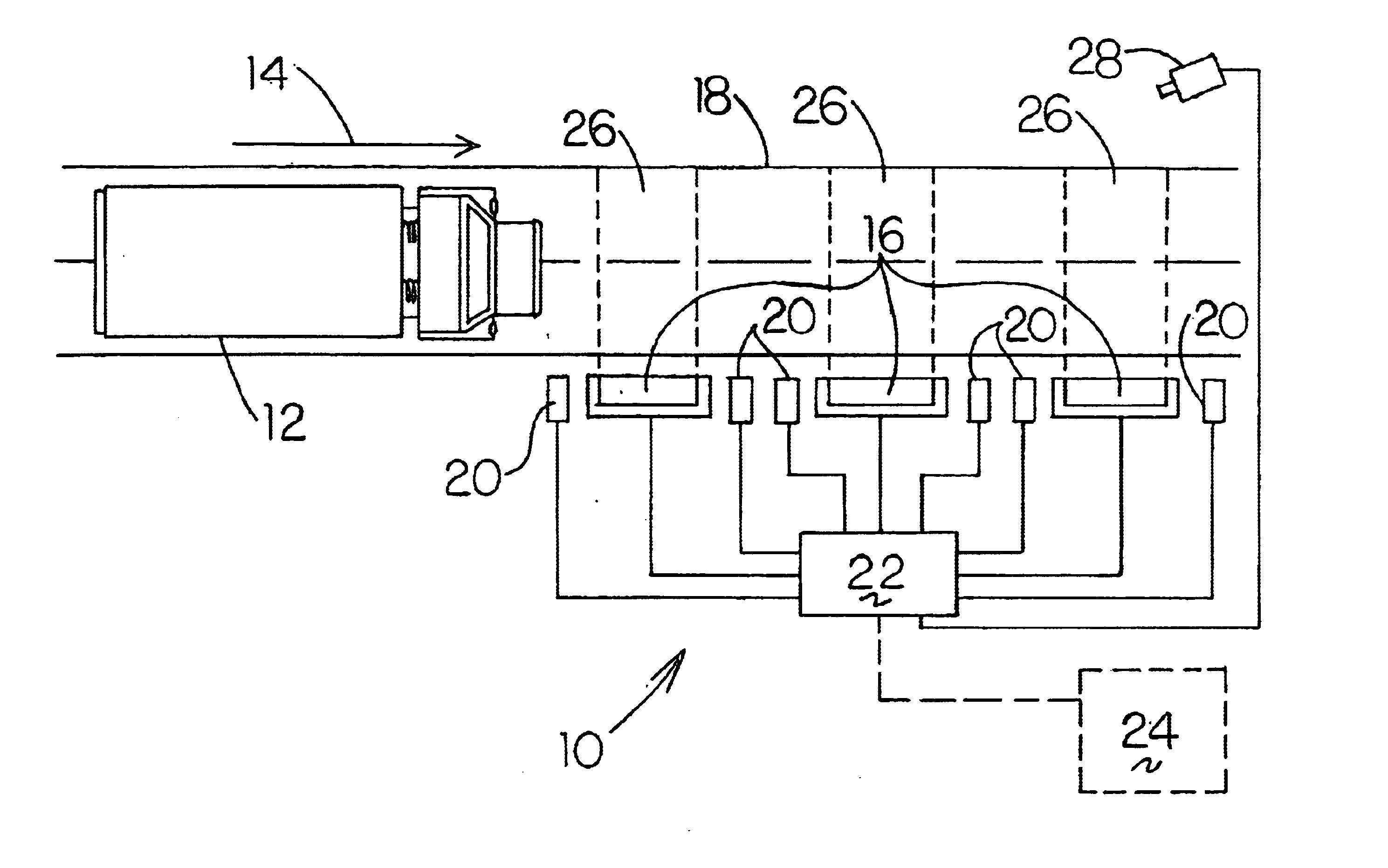
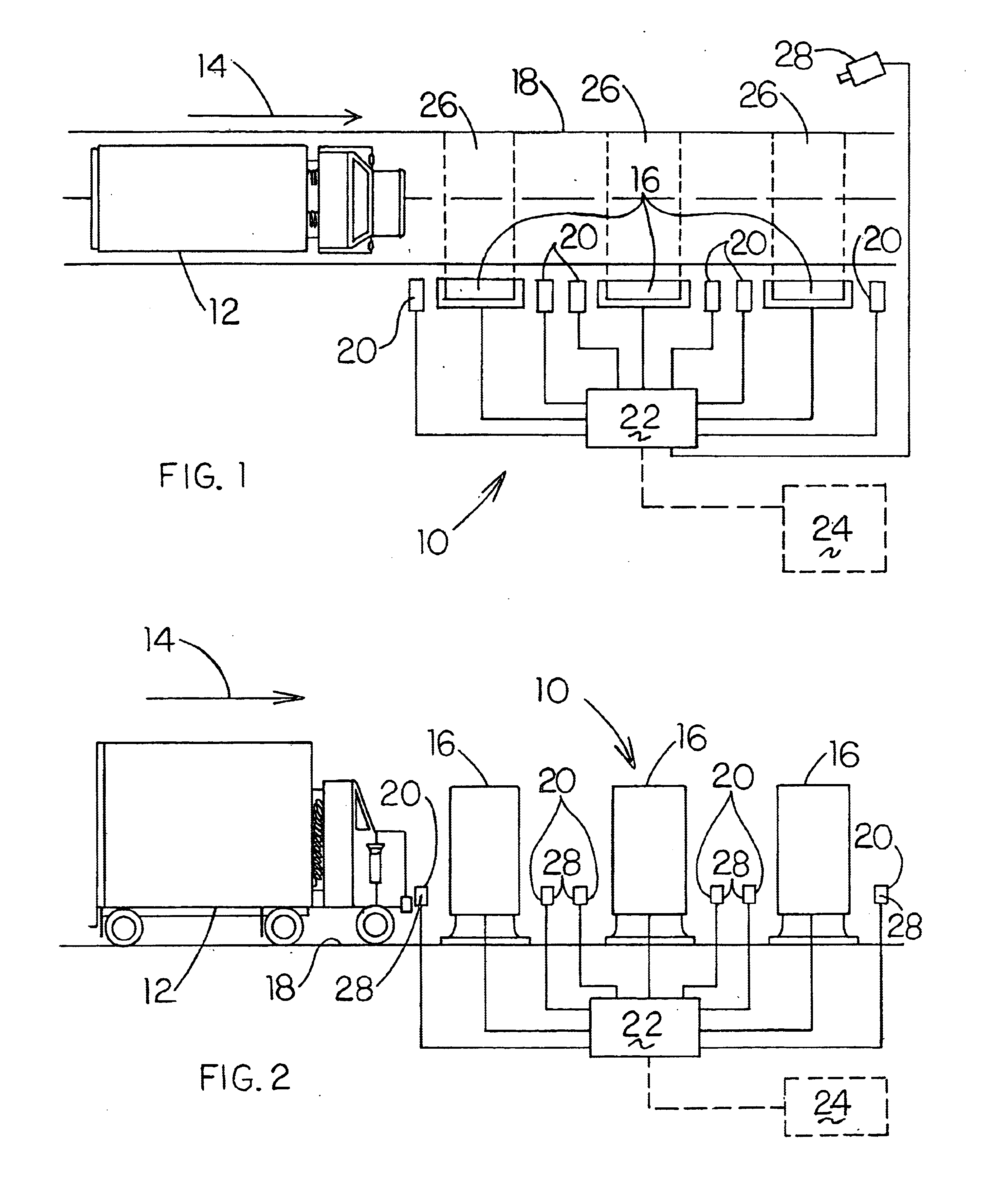
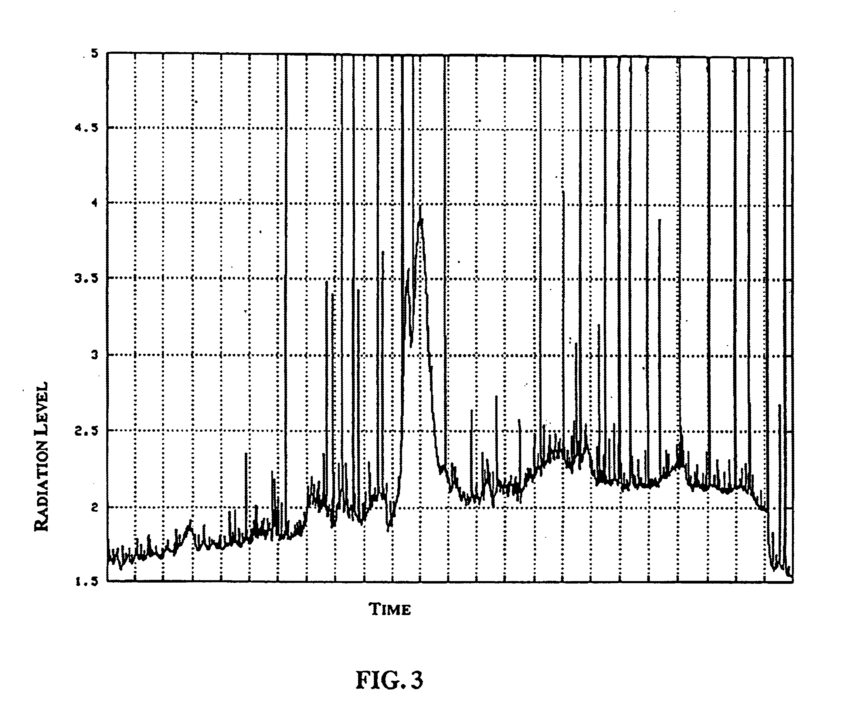
FIGS. 1-7 illustrate the new and improved radiation monitoring system 10 of the present invention. FIGS. 1 and 2 depict the system 10 of the invention in use. FIGS. 3-7 show diagrammatic graphical examples of readings taken from the system and the unique manner in which they are summed and averaged in order to detect radiation emitting objects moving at high speeds in light of background levels of radiation. Referring to FIGS. 1 and 2, the radiation monitoring system 10 for detecting moving radioactive sources is shown. It will be appreciated that the moving source may be a vehicle 12 such as a car, truck or train, or an object such as scrap moving along a conveyor belt, baggage or luggage moving through an airport luggage distribution system, or parcels and packages being routed at a mail distribution site even though the drawings and description following are specific to a vehicle.

A vehicle 12 is shown traveling in the direction of the arrow 14. The vehicle is scanned for ionizing...


PUM


Abstract

A radiation monitoring system for detecting levels of radiation emitted from moving objects traveling at a wide range of speeds, including the high speeds normally encountered with vehicles traveling on highways, interstates, thoroughfares, railroads and conveyors. At least two and preferably three ionizing radiation detectors are employed, spaced apart in series along the direction of travel of the moving object or vehicle. The object or vehicle is monitored for radioactivity and the results are transmitted and processed at a central location. The individual results from each detector for a particular object or vehicle are summed and averaged over the number of detectors used thereby clearly distinguishing the fluctuating background radiation detected at each detector from the consistent high levels of radiation detected from those moving objects or vehicles measured emitting radiation. The results are cooperatively linked by an identification system such as a web cam or other photographic device which obtains visual identification of the objects and vehicles emitting the abnormally high levels of radiation detected.

Description

BACKGROUND OF THE INVENTIONThe present invention relates to the detection of ionizing radiation, particularly to a method and apparatus for detecting ionizing radiation and moving sources, and more particularly to a method and apparatus for detecting high levels of ionizing radiation emitted from vehicles moving at high speeds along public roadways.The problem of detecting moving objects that emit ionizing radiation has become significant. Scrap metal moving into scrap yards and steel mills must not contain significant radioactive contamination. The result of a truckload, or railcar load of scrap metal with radioactive contamination moving into a scrap yard could be the decontamination of the yard at great cost. The result of a contaminated load of scrap metal moving into a steel mill could be the decontamination of the mill. High decontamination costs have been encountered in such situations. The scrap metal, with the hidden radioactive contamination, may be moving into the yard or...

Claims


Application Information

Patent Timeline
Patent Type & Authority Patents(United States)
IPC IPC(8): G01T1/00G01V5/00
CPCG01V5/0075
Inventor MALLETTE, MALCOLM C.
Owner MALLETTE MALCOLM C
Why Eureka
Try Eureka