Check patentability & draft patents in minutes with Patsnap Eureka AI!

Device for coding and decoding locations

a technology for coding locations and devices, applied in traffic control systems, navigation instruments, instruments, etc., can solve problems such as technical criticality, received information cannot be coded, and the transmission of geographic coordinates by itself is not sufficien

Inactive Publication Date: 2004-04-27
ROBERT BOSCH GMBH
View PDF5 Cites 14 Cited by
  • Summary
  • Abstract
  • Description
  • Claims
  • Application Information

AI Technical Summary

Benefits of technology

The present invention provides a device for coding locations that allows decoding of location information in the receiver even for different coding and decoding tables. The device can be used for various services such as road systems, rail systems, waterway systems, and so on. The device includes a coordinate portion and a declaration portion. The coordinate portion contains a plurality of coordinate pairs, one pair representing the coordinates of the coded location and at least one auxiliary point. The declaration portion contains the number of coordinate pairs, the position of the coordinate pair in the coordinate portion, and a type indication of the coded location. The device can also contain indications for the type of coding and tolerances of the coordinate pairs. The invention allows for the accurate positioning of locations using geographic coordinates, even if the transmitter and receiver have different degrees of precision. The device can be used to guide a user on a Saturday morning to the best route, taking into account traffic jams and streetcar stops. The invention also allows for the flexibility to adapt the decoding process to different circumstances.

Problems solved by technology

However, a transmission of geographic coordinates by itself is not sufficient since different locations can be found at one geographic position, for example, on bridges or in tunnels.
Because of those references, among other things, the maintenance and synchronization of this location database is technically critical.
However, received information can only be coded if the same location database has been used for the coding.

Method used


Image

  • Device for coding and decoding locations
  • Device for coding and decoding locations
  • Device for coding and decoding locations

Examples


Embodiment Construction

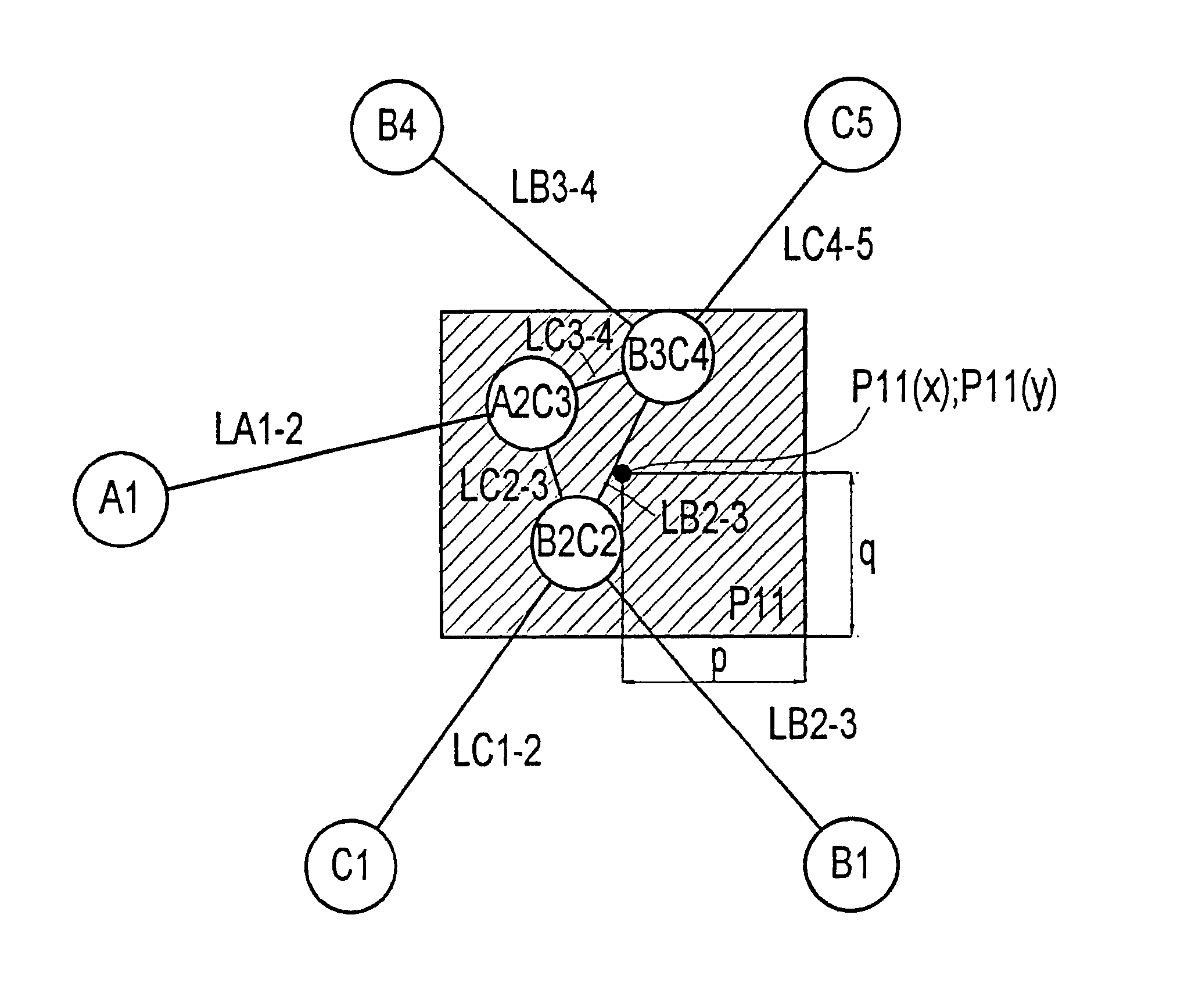
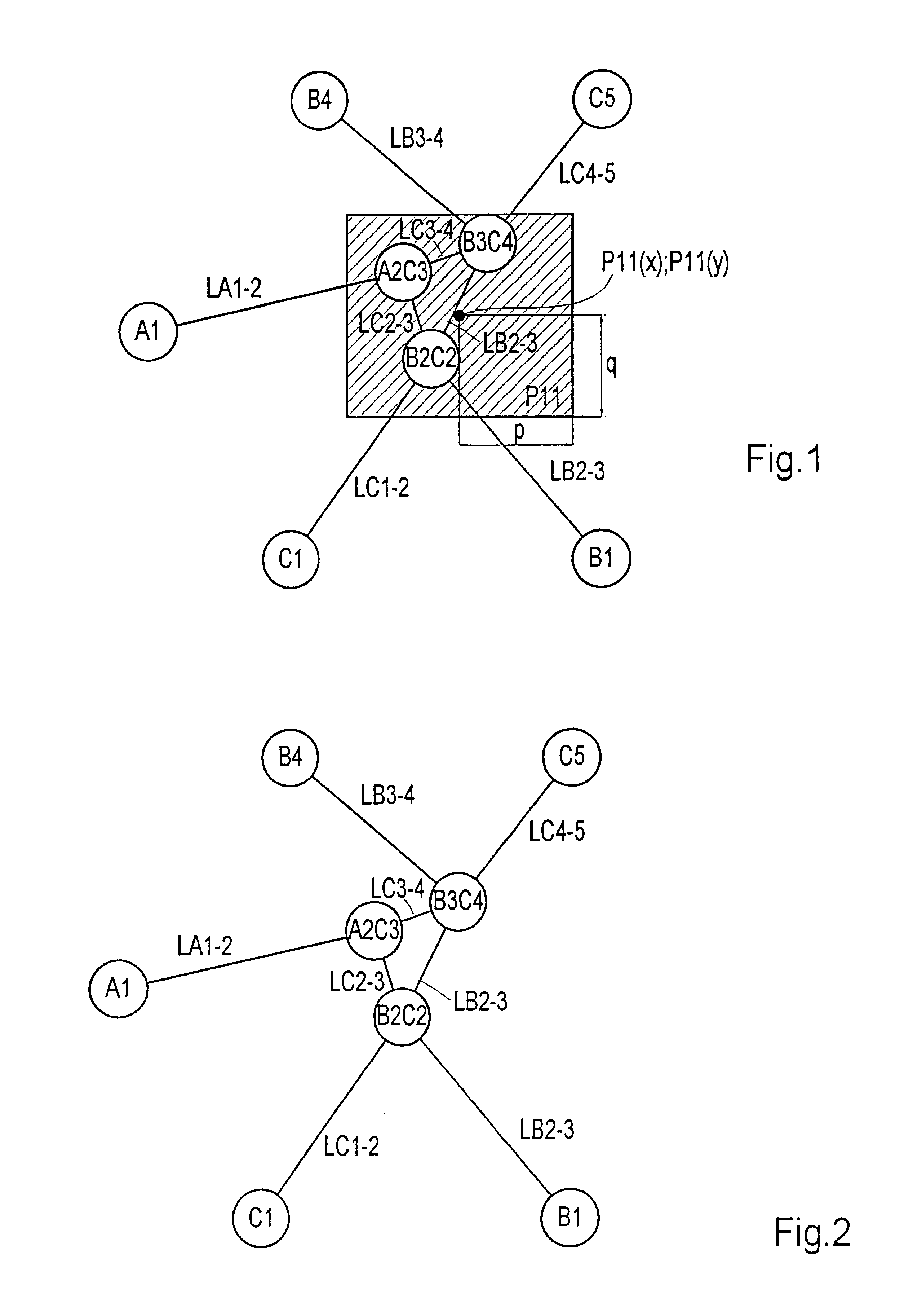
A digital roadmap, which is represented as a hypothetical example in FIG. 2, is used for the coding and decoding operations. To transmit information that refers, for example, to point A2C3 on street C in driving direction CS, this point must be coded. In this case, a specification of coordinates with relatively large tolerances is assumed. In addition to street C, which runs from C1 through points B2C2, A2C3 and B3C4 to point C5, FIG. 2 shows two other streets, namely a Street A between locations A1 and A2C3 and a Street B between locations B1, B2C2, B3C4 and B4. The sections between the streets are designated using a prefix of L and the indication of the particular locations connected by the street.

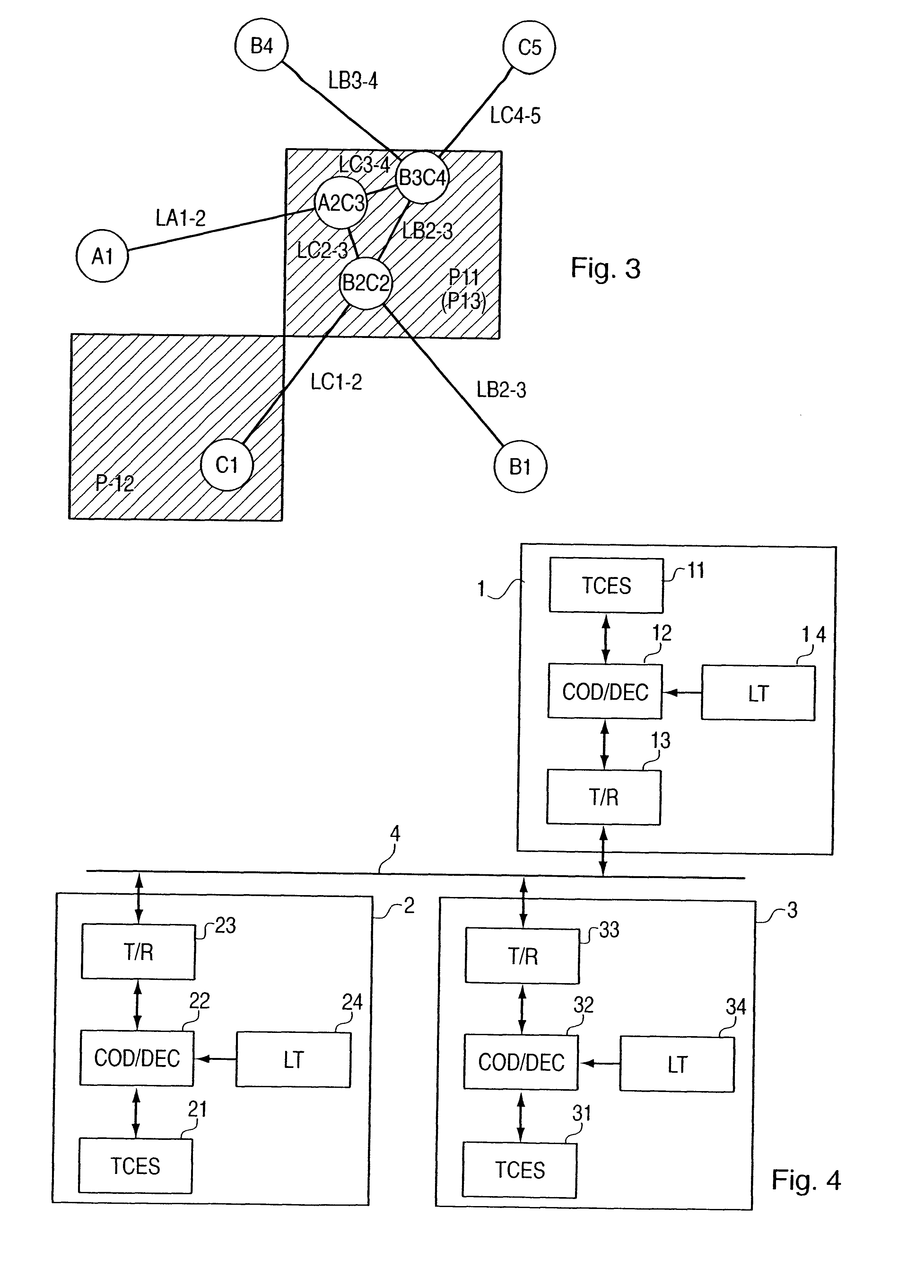
In addition to the road system according to FIG. 2, FIG. 1 shows the tolerance range of a point P11 having the coordinates P11(x); P11(y). This coding alone can be used to determine which of the locations falling within the crosshatched tolerance range is coded. Therefore an auxiliary po...


PUM


Abstract

A device for coding and decoding locations in a transportation network, providing that information concerning these locations are transmitted from one transmitter to one receiver. In the device, the code is composed of a declaration portion and a coordinate portion corresponding to each coded location. The coordinate portion includes a plurality of coordinate pairs, one coordinate pair representing the coordinates of the coded location stored on the transmitter side and at least one other coordinate pair representing an auxiliary point. The declaration portion includes at least the number of coordinate pairs contained in the coordinate portion, the position of the coordinate pair of the coded location in the coordinate portion, and an indication of the type of coded location. For decoding purposes, locations falling within the tolerance range of the received coordinate pairs are determined in a location database that contains the coordinates, the position at any time on the traffic route and additional location information. Of the specified locations, the ones situated on a common traffic route are selected; and of these selected locations, the one that falls within the tolerance range of the specified coordinate pair can be defined as the decoded location.

Description

FIELD OF INVENTIONThe present invention relates to a device for coding locations in a transportation network, information concerning the locations being transmitted from one transmitter to one receiver, and to a device for decoding received information, which signifies a location on a street and contains a plurality of coordinate pairs, each of which is given a tolerance range and of which at least one specific coordinate pair along with its tolerance range includes the location.BACKGROUND OF THE INVENTIONIn traffic control engineering systems, vehicles exchange information with central systems Via remote data transmission. This information exchange enables different applications, such as emergency call service, or, traffic information service, or, help with directions or dynamic guidance services, to be implemented. The transmission of location information is necessary for all these services. Location information can be used, for example, to depict the positions of vehicles, locati...

Claims


Application Information

Patent Timeline
Patent Type & Authority Patents(United States)
IPC IPC(8): G01C21/00G09B29/00G08C17/00G08G1/09G08C17/02H04B7/26G01S19/48
CPCG01C21/00G01S19/48G08C17/02G08G1/09G09B29/00H04B7/26G01C21/3889
Inventor HESSING, BERND
Owner ROBERT BOSCH GMBH
Features
  • R&D
  • Intellectual Property
  • Life Sciences
  • Materials
  • Tech Scout
  • Unparalleled Data Quality
  • Higher Quality Content
  • 60% Fewer Hallucinations
Learn More