Expandable underreamer/stabilizer

a stabilizer and underreamer technology, applied in the field of underreamers, can solve the problems of limiting the annular area available for cementing operations, affecting the affecting the strength and hydraulic capacity of the underreamer,

Inactive Publication Date: 2004-05-11
SMITH INT INC
View PDF19 Cites 399 Cited by
  • Summary
  • Abstract
  • Description
  • Claims
  • Application Information

AI Technical Summary

Benefits of technology

In one preferred embodiment, the expandable tool further includes at least one axial recess in the body and at least one moveable arm. The number of recesses corresponds to the number of moveable arms, such that each arm is stored in a corresponding recess when the tool is collapsed. Preferably the tool includes three such arms that are biased to a collapsed position by a spring. When the tool expands, the arms are translated axially upwardly, while simultaneously being extended radially outwardly from the body. Preferably, the arms are moved upwardly by a piston and extended outwardly along angled channels in the body. The expanded diameter of the tool is adjustable at the surface without requiring a change of components.

Problems solved by technology

Each new casing string is supported within the previously installed casing string, thereby limiting the annular area available for the cementing operation.
In some designs, these pivoted arms tend to break during the drilling operation and must be removed or "fished" out of the borehole before the drilling operation can continue.
The pocket recesses form large cavities in the underreamer body, which requires the removal of the structural metal forming the body, thereby compromising the strength and the hydraulic capacity of the underreamer.
Accordingly, these prior art underreamers may not be capable of underreaming harder rock formations, or may have unacceptably slow rates of penetration, and they are not optimized for the high fluid flow rates required.
The pocket recesses also tend to fill with debris from the drilling operation, which hinders collapsing of the arms.
If the arms do not fully collapse, the drill string may easily hang up in the borehole when an attempt is made to remove the string from the borehole.
Conventional underreamers have several disadvantages, including cutting structures that are typically formed of sections of drill bits rather than being specifically designed for the underreaming function.
Therefore, the cutting structures of most underreamers do not reliably underream the borehole to the desired diameter.
A further disadvantage is that adjusting the expanded diameter of a conventional underreamer requires replacement of the cutting arms with larger or smaller arms, or replacement of other components of the underreamer tool.
Another disadvantage is that many underreamers are designed to automatically expand when drilling fluid is pumped through the drill string, and no indication is provided at the surface that the underreamer is in the fully-expanded position.
A number of disadvantages are associated with this design.
However, the pass-through diameter of the drilling assembly at the eccentric underreamer portion barely fits within the lowermost casing string.
Further, due to directional tendency problems, these eccentric underreamer portions have difficulty reliably underreaming the borehole to the desired diameter.
With respect to a bi-center bit, the eccentric underreamer bit tends to cause the pilot bit to wobble and undesirably deviate off center, thereby pushing the pilot bit away from the preferred trajectory of drilling the well path.
A similar problem is experienced with respect to winged reamers, which only underream the borehole to the desired diameter if the pilot bit remains centralized in the borehole during drilling.

Method used


Image

  • Expandable underreamer/stabilizer
  • Expandable underreamer/stabilizer
  • Expandable underreamer/stabilizer

Examples


Embodiment Construction

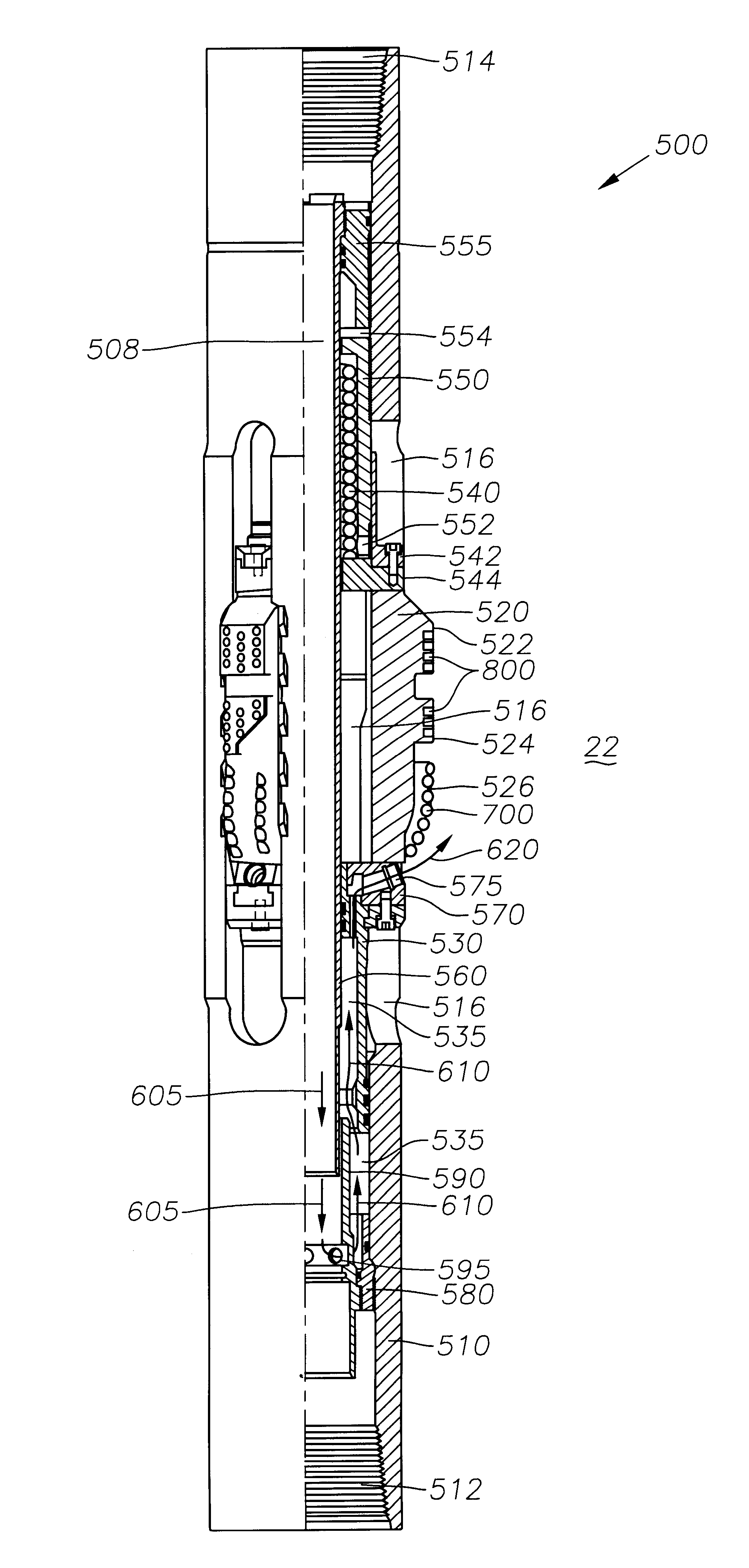
The preferred embodiments of the present invention feature a downhole expandable tool that may be used as an underreamer to enlarge the diameter of a borehole below a restriction, or alternatively, may be used as a stabilizer to control the directional tendencies of a drilling assembly in an underreamed borehole.

In one preferred embodiment, the expandable tool comprises a body with a flowbore therethrough in fluid communication with the wellbore annulus. The tool alternates between a collapsed position and an expanded position in response to differential fluid pressure. More specifically, the tool is biased to a collapsed position and expands in response to differential fluid pressure between the flowbore and the wellbore annulus. In the expanded position, the flow area between the flowbore and the wellbore annulus is larger than when the tool is in the collapsed position. The tool may expand automatically in response to differential fluid pressure, or may be constructed so that it ...


PUM


Abstract

A downhole tool that functions as an underreamer, or alternatively, as a stabilizer in an underreamed borehole. The tool includes one or more moveable arms disposed within a body having a flowbore therethrough in fluid communication with the wellbore annulus. The tool alternates between collapsed and expanded positions in response to differential fluid pressure between the flowbore and the wellbore annulus. In one embodiment, the tool moves automatically in response to differential pressure. In a second embodiment, the tool must be selectively actuated before it is moveable. When the tool expands, the arms are preferably translated axially upwardly, while simultaneously being extended radially outwardly from the body. The expanded tool diameter is adjustable at the surface without changing components. The arms may include borehole engaging pads that comprise cutting structures or wear structures or both, depending upon the function of the tool.

Description

Not Applicable.Not Applicable.1. Field of the InventionThe present invention relates generally to underreamers used for enlarging a borehole below a restriction to result in a borehole that is larger than the restriction. The present invention also relates generally to stabilizers used for controlling the trajectory of a drill bit during the drilling process. More particularly, the present invention relates to an expandable tool that may function as an underreamer, or alternatively, may function as a stabilizer in an underreamed portion of borehole. Still more particularly, the present invention relates to an expandable tool having arms that expand when a piston is exposed to fluid circulating through the borehole.2. Description of the Related ArtIn the drilling of oil and gas wells, concentric casing strings are installed and cemented in the borehole as drilling progresses to increasing depths. Each new casing string is supported within the previously installed casing string, there...

Claims


Application Information

Patent Timeline
Patent Type & Authority Patents(United States)
IPC IPC(8): E21B17/00E21B17/10E21B10/26E21B10/32
CPCE21B7/067E21B10/322E21B17/1014E21B10/26E21B10/32E21B17/10
Inventor DEWEY, CHARLES H.XU, WEI
Owner SMITH INT INC
Why Eureka
Try Eureka