
Method for cooling an arc lamp

a technology of arc lamps and cooling tubes, which is applied in the direction of lighting and heating equipment, instruments, transportation and packaging, etc., can solve the problems of arc instability, air flow can contribute to arc instability and flicker, and arc has a tendency to wander at high frequencies

Inactive Publication Date: 2004-05-18
IMAX CORP
View PDF11 Cites 17 Cited by
  • Summary
  • Abstract
  • Description
  • Claims
  • Application Information

AI Technical Summary

Benefits of technology

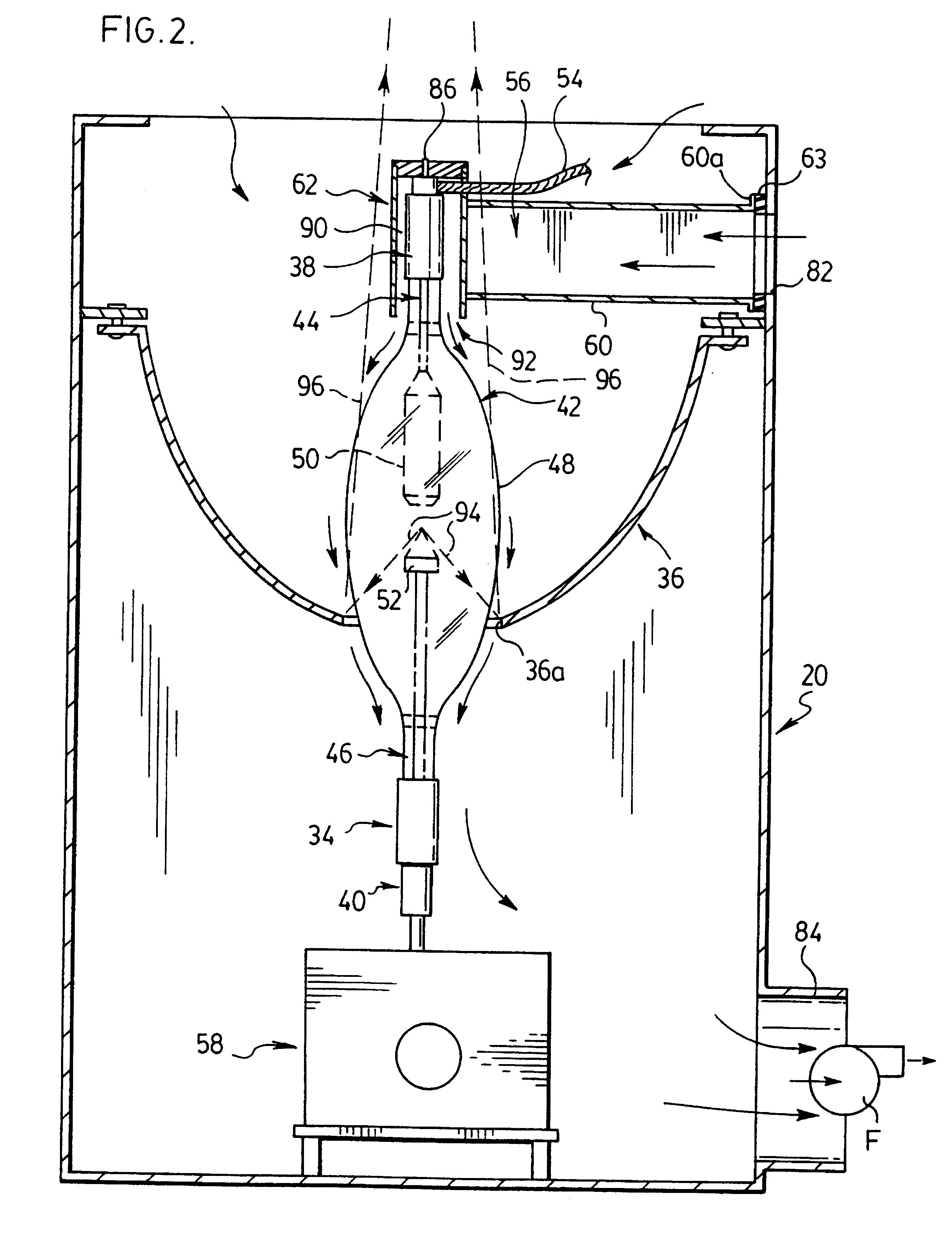
As indicated previously, the invention is based on the recognition that precise control of cooling air flow over the surface of the lamp is critical to arc stability. The annular air gap between shroud and the end portion of the lamp (usually the anode end) creates a "sheet" of laminar air flow which tends to "adhere" to the surface of the bulb, thereby providing precise cooling. In practice, it has been found that only one cooling fan is necessary for a projection lamphouse and the that air flow can be precisely controlled to provide adequate cooling while avoiding excessive air flow (which could lead to unwanted arc movement).
Preferably, the shroud itself is carried by a support arm that extends inwardly from a wall of the lamphouse. The arm is hollow and communicates with the air inlet to the shroud at one end, and with the air inlet to the lamphouse at its opposite end. The cooling air then flows along the arm and into the shroud. The shroud preferably is positioned asymmetrically with respect to the end of the lamp so that the gap between the shroud and the lamp varies from a maximum adjacent the air inlet to a minimum at the opposite side of the end of the lamp. This offset addresses the tendency of air to move faster near the inlet. The wider gap reduces the air speed while the narrower gap at the opposite side increases the speed of the air. Overall, the result is a more uniform air flow around the entire circumference of the lamp.

Problems solved by technology

If the air flow is too great, gas (xenon) turbulence can be created within the bulb itself, causing arc instability.
In the case of a projection lamp, this instability can be seen as an annoying flicker on the projection screen.
It has been found that the air flow can also contribute to arc instability and flicker if it is non-uniform over the surface of the lamp bulb.
Where the lamp is oriented vertically (usually anode upwards) it has been found that the arc has a tendency to wander at high frequencies, which is especially noticeable as flicker on the projection screen.

Method used


Image

  • Method for cooling an arc lamp
  • Method for cooling an arc lamp
  • Method for cooling an arc lamp

Examples


Embodiment Construction

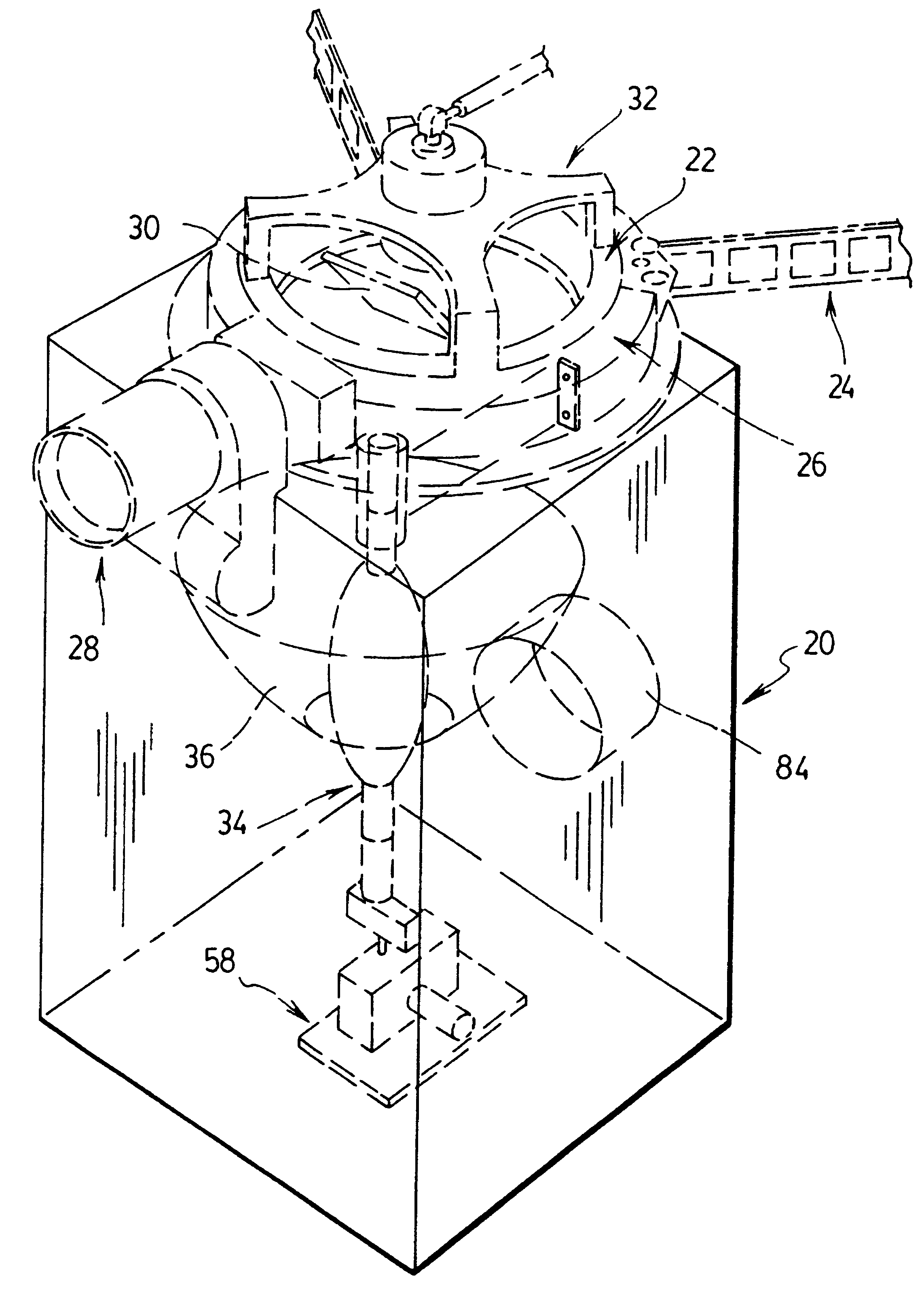
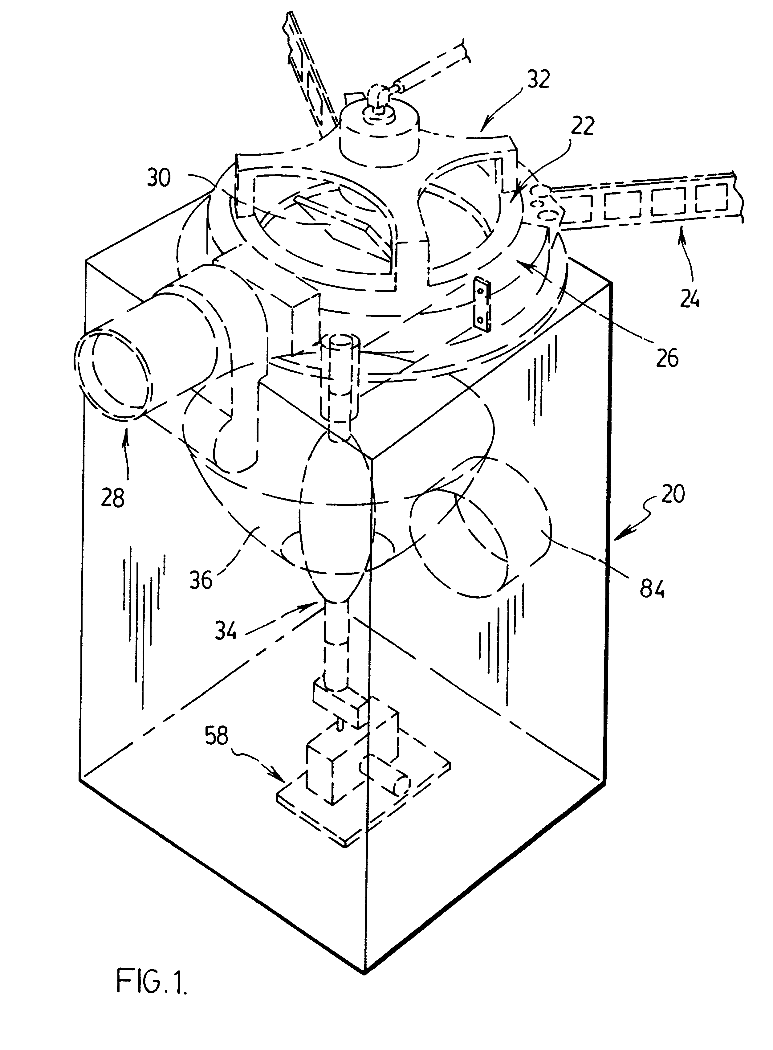
FIG. 1 shows generally a motion picture projector of the form disclosed in the '750 U.S. patent (Gibbon et al.) referred to previously. Reference may be made to the disclosure of that patent for details of the projector mechanism. For present purposes, it is sufficient to note that the projector is of the so-called "rolling loop" type. Reference numeral 20 denotes a lamphouse that is located below a rotor 22 of the projector. Film transported through the projector is indicated at 24 and passes around a portion of the surface of the rotor 22 inwardly of a stator 26. A projection lens assembly is indicated at 28. Light from the lamphouse 20 is directed upwardly and reflected forwardly by a mirror 30, through the film 24 and then through the projection lens 28. Reference numeral 32 denotes a "spider" that rotationally supports the rotor 22 from above.

Lamphouse 20 is essentially a rectangular box or enclosure within which is supported a projection lamp 34 and a light collector 36. As be...


PUM


Abstract

A xenon arc lamp for a motion picture projector is cooled by providing the anode end of the lamp with a shroud that forms part of a support for that end of the lamp. Cooling air flows into the shroud along the support arm and enters the shroud through a slot in its side wall. The shroud provides an annular air space around the anode end of the lamp and has an annular air outlet through which the cooling air leaves as a "sheet" of laminar air flow which tends to adhere to the surface of the bulb, thereby providing precise cooling. In this way, arc instability is avoided or minimized, while lamp life is extended.

Description

This invention relates generally to arc lamps primarily but not exclusively for use as projection lamps in motion picture projectors.Xenon arc lamps generate significant heat in operation and must be cooled in order to achieve acceptable lamp life. In an air-cooled projector, the lamp is located in a lamphouse and sufficient air flow must be provided within the lamphouse to remove heat generated by the arc lamp. An example of a projector having an air cooled xenon arc lamp is disclosed in U.S. Pat. No. 5,587,750 (Gibbon, et al.). The patent does not provide specific disclosure of how the lamp is cooled but FIG. 1 of the drawings does show (at 46) a hose through which cooling air for the lamphouse (42) is exhausted from the projector. The disclosure of the Gibbon et al. patent is incorporated herein by reference.A xenon arc lamp typically has a glass envelope enclosing an anode and a cathode between which the arc is struck. An atmosphere of inert xenon gas under pressure is provided ...

Claims


Application Information

Patent Timeline
IPC IPC(8): F21V29/00F21V29/02H01J61/52H01J61/02F21V29/60G03B21/16
CPCF21V29/02H01J61/526H01J61/86F21V29/673G03B21/2026
Inventor GIBBON, MICHAEL A.TOPORKIEWICZ, MARIAN
Owner IMAX CORP
Learn More