Safety contact strip

a contact strip and safety technology, applied in the direction of contact operating parts, electrical equipment, door/window fittings, etc., can solve the problems of comparatively thin contact layer, and comparatively poor electrical conductor performance, so as to achieve the effect of reducing the risk of epdm damage, and reducing the service life of the contact layer

Inactive Publication Date: 2004-05-25
ASO ANTRIEBS UND STEUERUNGSTECHN
View PDF7 Cites 29 Cited by
  • Summary
  • Abstract
  • Description
  • Claims
  • Application Information

AI Technical Summary

Benefits of technology

According to the invention, the profile, the switching chamber and the switching areas, each with at least one embedded conductor, are formed in one piece. As compared with a two-part formation, with a contact-maker profile and a pushed-in safety contact strip, a one-piece formation is advantageous from technical production-related aspects. In particular, the measures of the one-piece formation also allow the thickness of the walls of the switching chamber to be kept relatively small, without there being the risk of soiling in the event of breakage of the outer jacket. The measure of a thinner wall of the switching chamber also significantly improves the response of the safety contact strip under a switching load. In particular, the omission of a separately formed enclosure of the switching layers produces a significant saving of material.
In the case of a preferred embodiment, it is provided that lips projecting in front of the shoulder for engagement of the outer jacket. In this respect, it is envisaged in particular that an outer lip covers the abutting edge against the outer jacket of the profile and, if appropriate, is in turn adhesively bonded or fused with the latter. This produces very reliable sealing of the ends at the end faces of the safety contact strip according to the invention. Lips projecting within the profile for an inner engagement of the outer jacket have to make allowance in their formation for the webs of the profile and, if appropriate, be interrupted, and are preferably formed as simple projecting bar-like portions.

Problems solved by technology

These switching layers may also consist of an EPDM material, which is often a comparatively poor electrical conductor.
Although in the case of safety contact strips of this type only a low switching load is necessary, there is the great risk of soiling of the switching layers, for example in the event of breakage of the profile.
Since these safety contact strips can be produced from a conductive material and a non-conducting EPDM material, which materials can also be coextruded to form these safety contact strips, there is the great risk of the comparatively thin, outer protective layer of the non-conducting EPDM material not being correctly formed and the conductive layer remaining outwardly uninsulated and easily liable to damage.
It can be regarded as disadvantageous in this respect that only made-up safety contact strips of a specific length are then available.
In this region, reliable operability of the contact strip is often no longer obtained, since a deformation of the switching chamber often cannot take place.

Method used


Image

  • Safety contact strip
  • Safety contact strip
  • Safety contact strip

Examples


Embodiment Construction

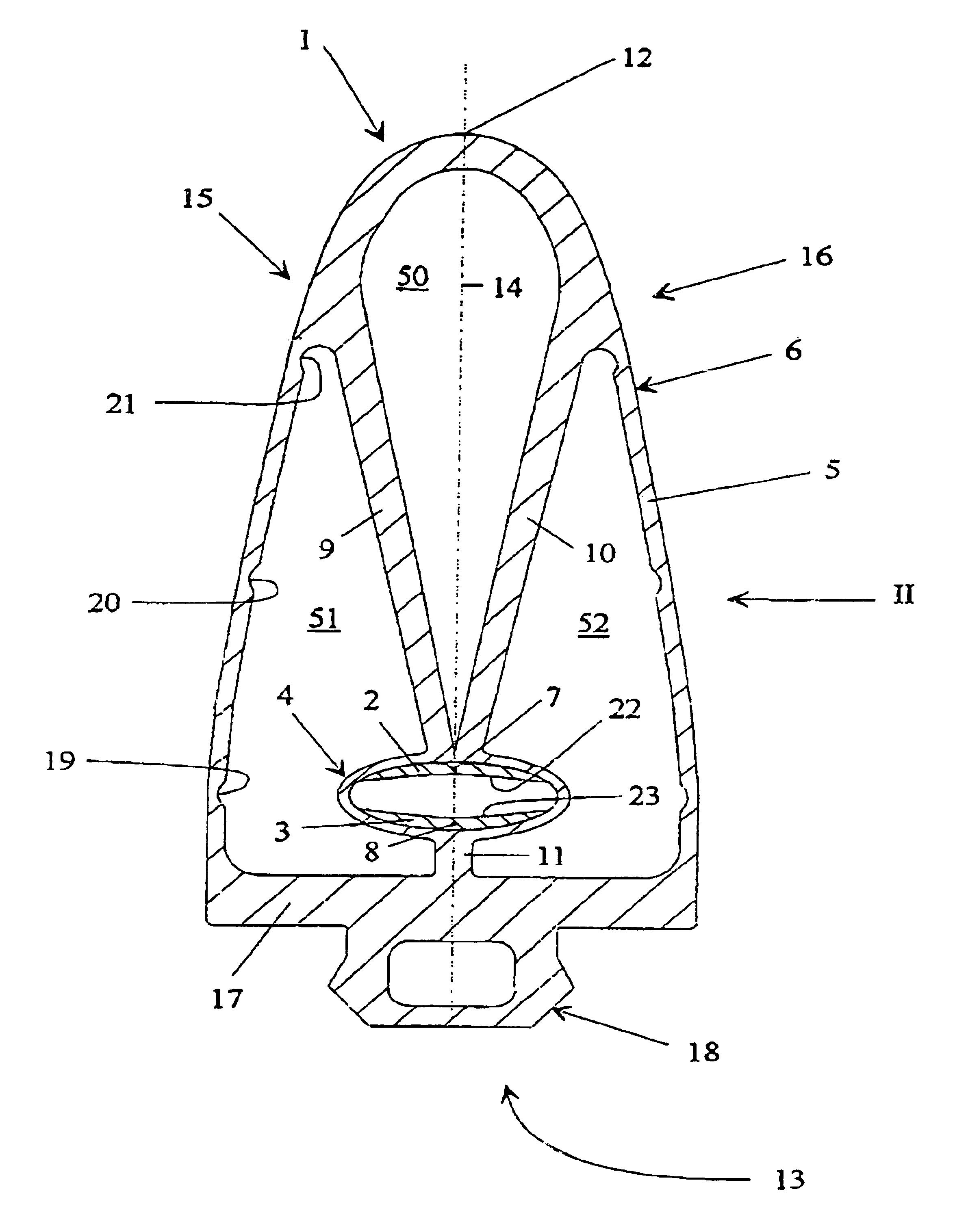
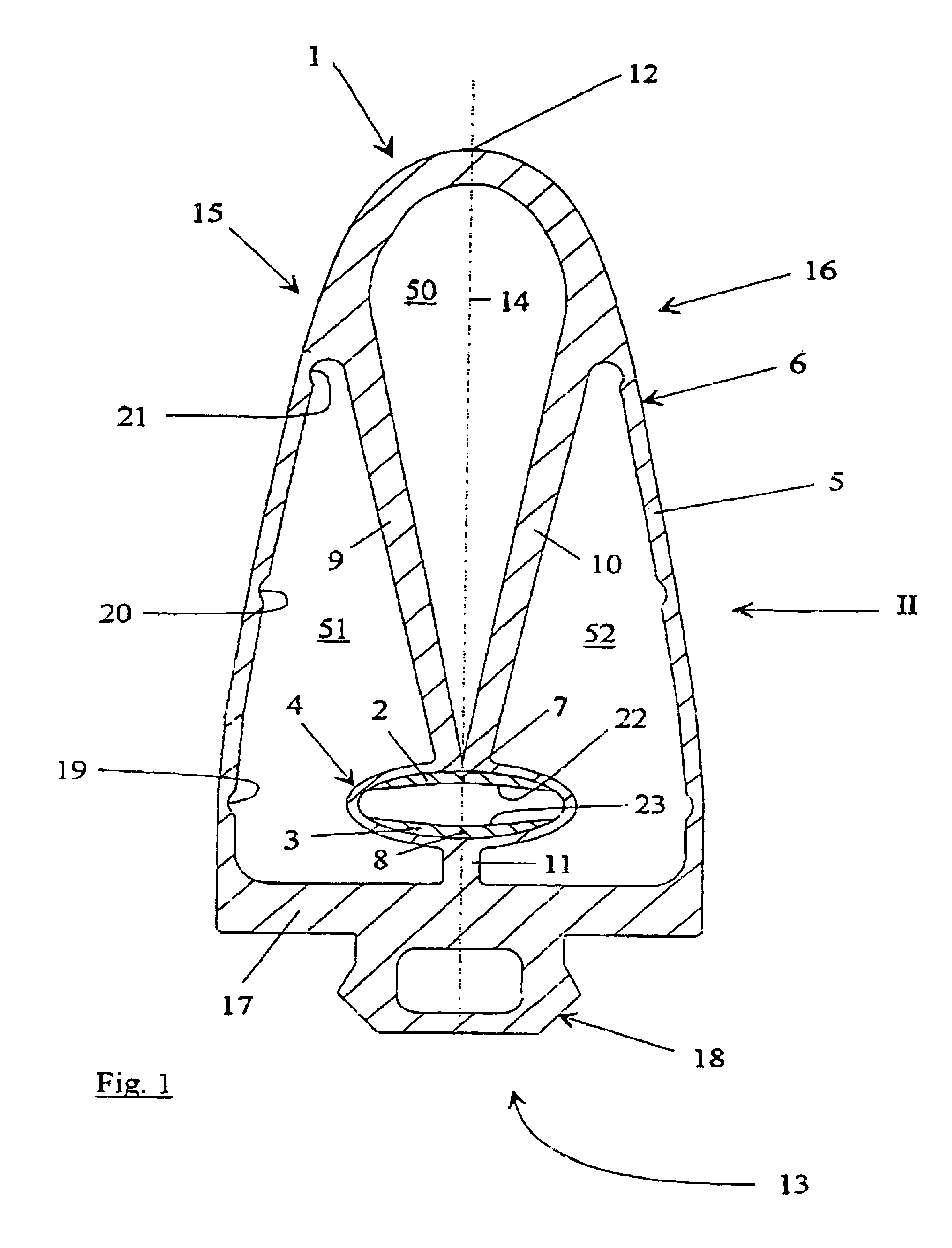
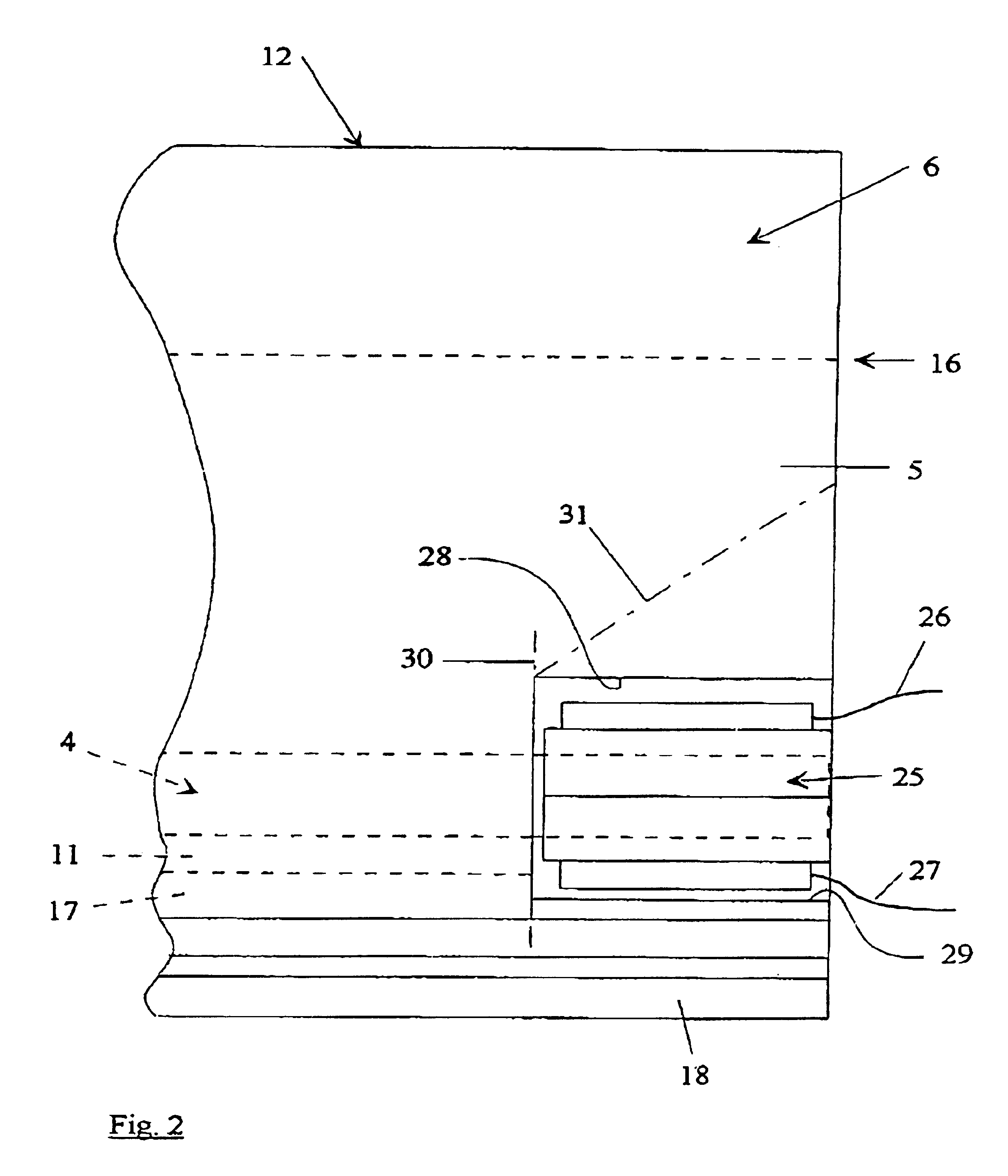
The safety contact strip 1 shown in FIGS. 1 and 2 has two conducting switching layers 2, 3 in a closed switching chamber 4, which is arranged within an outer jacket 5 of a profile 6. The profile 6, the switching chamber 4 and the switching layers 2, 3, each with at least one embedded conductor 7, 8, are formed in one piece.

Arranged on the base 17 of the profile 6, on the fastening side 13, there is also a fitting piece 18, for clamping or pushing into a C holding profile, for example an aluminum profile.

In particular, it may be provided that the profile 6 is produced from a thermoplastic elastomer, a TPE material, that the conducting layers 2, 3 consist of an EPDM material, an ethylene / propylene-diene terpolymer, and that the in each case at least one conductor 7, 8 embedded in the conducting layers 2, 3 is a metallic conductor, for example a copper wire, a stranded copper wire, a metal mesh or the like, which materials and conductors form the safety contact strip 1 according to the...


PUM


Abstract

The invention relates to a safety contact strip (1) that is regularly used as a closing edge safely device in squeeze and shear areas, for example, gates, machines or the like, having at least two conductive switch layers (2,3) in a non-conductive closed switching chamber (4) located inside a profile (6) that forms an outer jacket (5). In order to enhance quality while preserving a relatively simple structure of said strip, the profile (6), the switching chamber (4) and the switch layers (2,3) are configured as a single piece having at least one built-in conductor (7,8). In order to ensure safe switching even in case of low switch loads and unexpected direction, the switching chamber (4) is kept free in a cross section by spoke-shaped webs (9,10,11). The invention also provides for a cap for closing the front side of the safety contact strip.

Description

1. Field of the Invention2. Description of the Related ArtThe invention relates to a safety contact strip having at least two conducting switching layers in a non-conducting, closed switching chamber within a profile forming an outer jacket.Safety contact strips are often used as closing edge safety devices at pinching and shearing points. Fitted on gates, machines and handling equipment, persons and material are protected by such safety contact strips. For this purpose, the known safety contact strips are usually held on a respective fastening side in an aluminum carrier profile.A safety contact strip of the generic type has a contact-maker profile which is held in a carrier profile and in which a separately formed safety contact strip is accommodated in a switching chamber within the outer jacket of the profile. The special shaping of the contact-maker profiles, consisting in particular of an EPDM or an NBR rubber, protects the safety contact strip lying in the switching chamber f...

Claims


Application Information

Patent Timeline
Patent Type & Authority Patents(United States)
IPC IPC(8): E05F15/00E05F15/40E05F15/44H01H3/14
CPCH01H3/142E05F15/44E05Y2600/40
Inventor FRIEDRICH, HELMUTMEYER, PAUL
Owner ASO ANTRIEBS UND STEUERUNGSTECHN
Why Eureka
Try Eureka