Integrated type gas-insulated switching apparatus

a switching apparatus and integrated technology, applied in the direction of contact mechanisms, non-enclosed substations, substations, etc., can solve the problems of increasing the cost of replacement work, requiring a great deal of transportation work, and longening the time required for replacement work

Inactive Publication Date: 2004-06-01
KK TOSHIBA
View PDF3 Cites 6 Cited by
  • Summary
  • Abstract
  • Description
  • Claims
  • Application Information

AI Technical Summary

Benefits of technology

Another object of the present invention to provide an integrated type gas-insulated switching apparatus that is capable of being applied to a power transmission system with double-bus bar configuration, and being used to select one of the double-busbars without damaging the essential role of the double-busbar configuration.
According to one aspect of the present invention, the switching devices can be easily separated from or connected to the conductive container as a single unit, so that, when a single switching device causes malfunction, it is extremely easy to replace only the switching device causing malfunction.

Problems solved by technology

This makes the replacement cost increase.
In addition, when replacing the disconnecting switches, it is necessary to disassemble the disconnecting switches on site and reassemble new disconnecting switches thereon, lengthening the time required for the replacement work.
When, on the other hand, replacing the entire apparatus including the disconnecting switches, because of transporting a large apparatus in which the disconnecting switches are assembled, the transporting work requires tremendous cost.
This causes insulation breakdown in the disconnecting switch to be short-circuited to the earth, with the result that the remaining switching point connected to the remaining disconnecting switch also loses its disconnecting function.
Accordingly this makes it impossible to transmit power for all systems connected via no other switching points to the gas compartment of each of the disconnecting switches.
That is, both operations of the double-busbars stop so that it is difficult to fulfill the object of the double-busbar configuration allowing, when one of the double-busbars does not transmit power, the other thereof transmits power.

Method used


Image

  • Integrated type gas-insulated switching apparatus
  • Integrated type gas-insulated switching apparatus
  • Integrated type gas-insulated switching apparatus

Examples


first embodiment (fig.1)

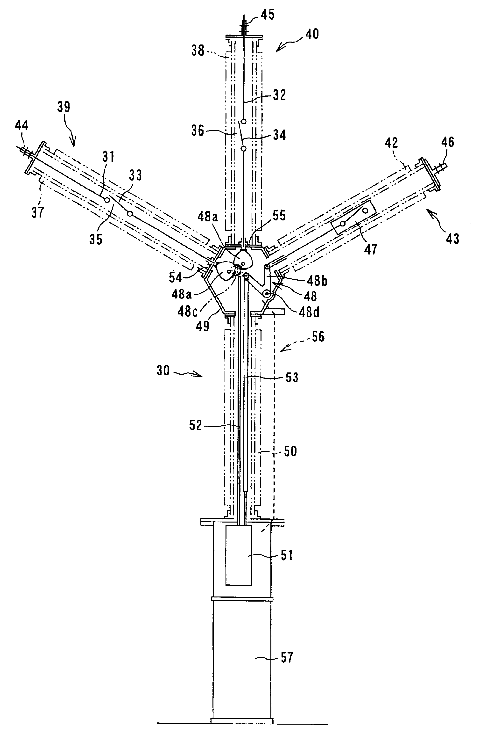
First Embodiment (FIG. 1)

FIG. 1 is a cross sectional view illustrating a substantially entire integrated type gas-insulated switching apparatus according to a first embodiment of the present invention.

As shown in FIG. 1, an integrated type gas-insulated switching apparatus 30 of the first embodiment is provided with disconnecting contacts (switching points) 35 and 36 that comprise stationary electrodes 31 and 32 and movable electrodes 33 and 34, respectively.

The movable electrodes 33 and 34 can be contacted with the stationary electrodes 31 and 32 and separated therefrom.

The integrated type gas-insulated switching apparatus (hereinafter, referred to simply as switching apparatus) 30 is also provided with insulated containers 37 and 38 in which the disconnecting contacts 35 and 36 are housed, whereby the insulated containers 37 and 38 housing the disconnecting contacts 35 and 36 constitute two disconnecting switches 39 and 40, respectively. Each of the insulated containers 37 and 38 ...

second embodiment (fig.2)

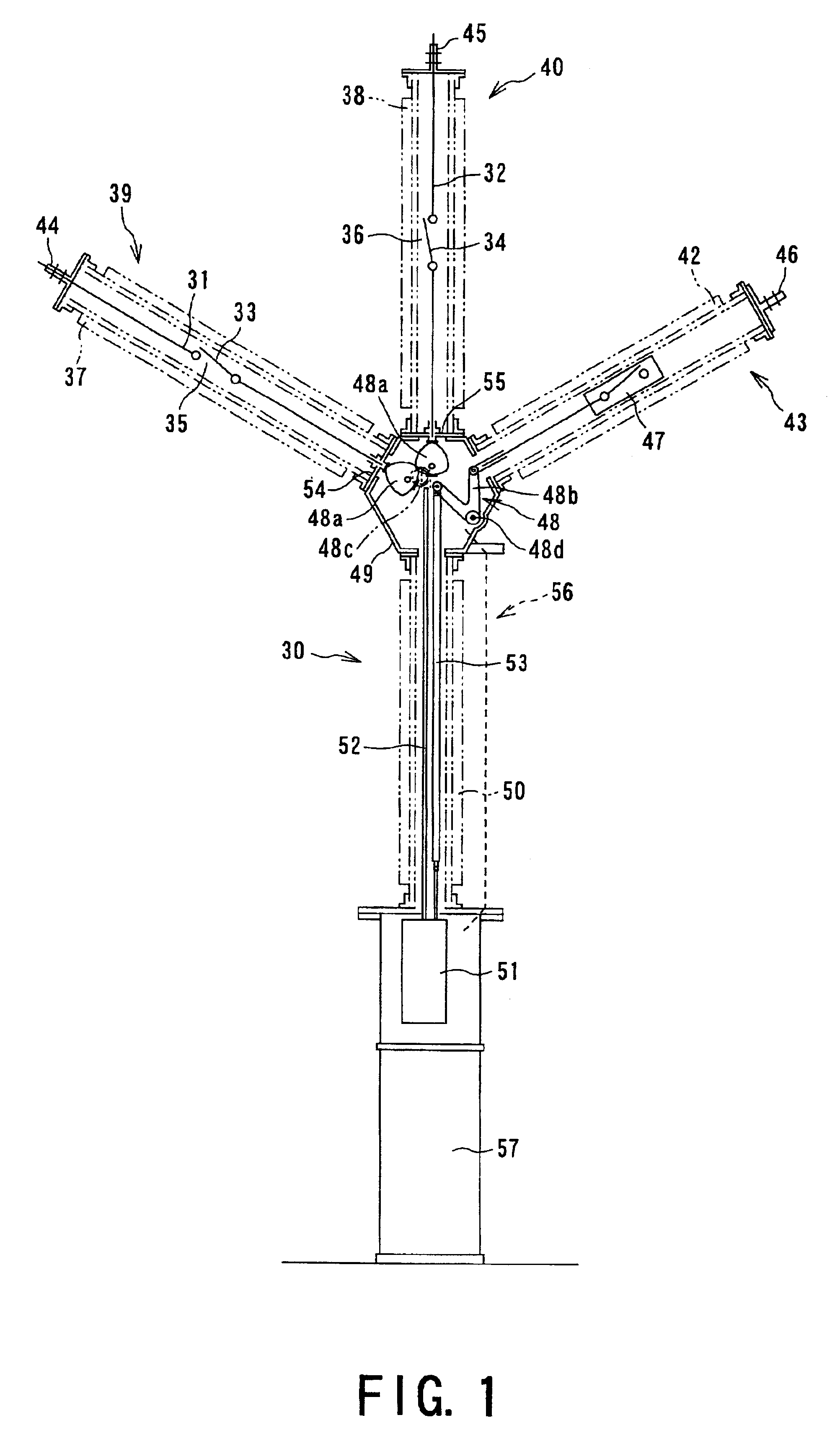
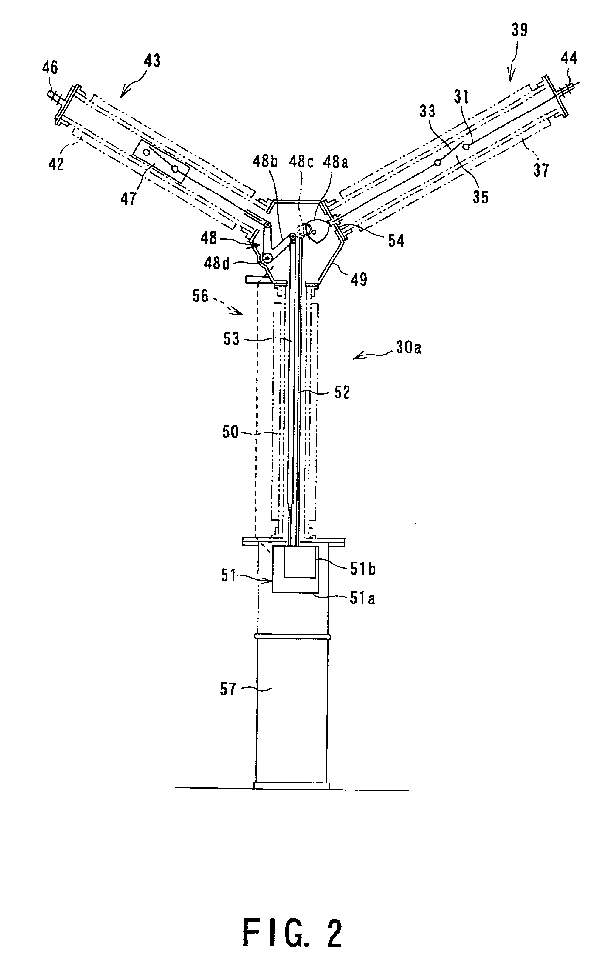
Second Embodiment (FIG. 2)

FIG. 2 is a cross sectional view illustrating a substantially entire integrated type gas-insulated switching apparatus 30a according to a second embodiment of the present invention.

Incidentally, elements of the switching apparatus 30a in FIG. 2 that are substantially the same as those of the switching apparatus 30 are given the same or similar reference numerals in FIG. 1, so that descriptions of the elements are simplified or omitted.

As shown in FIG. 2, the integrated type gas-insulated switching apparatus 30a of the second embodiment comprises the disconnecting switch 39 and the circuit breaker 43 which are connected to the metal container 49 in a diagonal layout so as to have a substantially V-shape.

That is, each of the disconnecting switch 39 and the circuit breaker 43 is connected at each one end with an exterior of the switching apparatus 30a by each of the external terminals 44 and 46.

The disconnecting switches 39 and the circuit breaker 43 are disco...

third embodiment (fig.3)

Third Embodiment (FIG. 3)

FIG. 3 is a cross sectional view illustrating a substantially entire integrated type gas-insulated switching apparatus 30b according to a third embodiment of the present invention.

Incidentally, elements of the switching apparatus 30b in FIG. 3 that are substantially the same as those of the switching apparatus 30a are given the same or similar reference numerals in FIG. 2, so that descriptions of the elements are simplified or omitted.

As shown in FIG. 3, the integrated type gas-insulated switching system 30b of the second embodiment comprises control rod guide members 52a and 53a provided to the upper side of the insulated container 50. In this embodiment, the control rod guide members 52a and 53a are mounted on the bottom surface of the metal container 49.

The control rod guide members 52a and 53a are adapted to individually guide the upper end portion of the control rods 52 and 53, respectively. That is, each of the control rod guide members 52a and 53a is ...


PUM


Abstract

In an integrated type gas-insulated switching apparatus, a plurality of switching devices are provided. Each of switching devices includes a contact and an insulated container in which the contact is contained. The contact comprises electrodes adapted to be contacted with each other and separated therefrom. The insulated container is filled with an insulating gas. A conductive container is provided, to which the plurality of switching devices are connected, respectively. An insulated structure supports the conductive container.

Description

1. Field of the InventionThe present invention relates to an integrated type gas-insulated switching apparatus for electrical power systems, which has a container made of an insulating material and is filled with an insulating gas. More particularly, the present invention relates to an integrated type gas-insulated switching apparatus that includes a plurality of switching devices.2. Description of the Related ArtConventionally, various integrated type gas-insulated switching apparatuses are well known, and a typical example thereof is described in U.S. Pat. No. 5,841,087, which is shown in FIG. 18.With the integrated type gas-insulated switching apparatus shown in FIG. 18, an isolating switch 1 is housed in a grounded metal housing 2 filled with an insulating gas, such as SF.sub.6. Stationary electrodes 3 and 4 forming switching points (contacts) are fixed to insulating spacers, and are fixed to the grounded metal housing 2 by flanges 5 and 6.On the other hand, a stationary electro...

Claims


Application Information

Patent Timeline
Patent Type & Authority Patents(United States)
IPC IPC(8): H02B5/06H02B5/00H02B13/035H02B13/02
CPCH01H33/122H01H33/42H01H33/56H02B5/06H02B13/035H01H31/003H01H33/008
Inventor MURAKI, SACHIOMURASE, HIROSHIOHARA, REIJIKOBAYASHI, AKIOTAKAGI, HIROKAZU
Owner KK TOSHIBA
Why Eureka
Try Eureka