Load detection structure for vehicle seat

a technology for vehicle seats and detection structures, applied in the direction of instruments, force/torque/work measurement apparatuses, tractors, etc., can solve the problems of excessive vertical movement of seats, high frequency, and objectionable noise generation

Inactive Publication Date: 2004-06-15
TACHI S CO LTD
View PDF10 Cites 31 Cited by
  • Summary
  • Abstract
  • Description
  • Claims
  • Application Information

AI Technical Summary

Benefits of technology

with such an arrangement that, when an excessive great load is applied to said seat, the vertical movement of both said buffer cover means and free end portion unit due to said excessive great load is limited by said vertical movement limiting means, after which, the excessive vertical movement of said cover means and free end portion is prevented by said stopper means.
Preferably, the vertical movement limiting means may comprise a limiter ring member of generally rectangular shape having an upper portion defining an upper limit in the limited space and a lower portion defining a lower limit in the limited space, so that the buffer cover means of the load detection unit is brought to contact with one of the upper and lower portions of limiter ring member when said excessive great load is applied to the seat, thereby limiting the vertical movement of load detection unit.

Problems solved by technology

The excessive vertical movement of seat is not only due to a traffic accident such as a collision, but also due to an instantaneous great load which is caused when a relatively heavy passenger suddenly sits on the seat, or due to extremely hard vertical vibrations or extraordinary instantaneous input of a great load which is caused during running of a vehicle on a rough road or when the vehicle falls in recesses in the road.
However, the conventional vertical movement restriction mechanism is formed by rigid constituent elements, which means that a great impact and contact will easily be caused among the parts in the abovementioned great load exertion cases and therefore, an objectionable noise will be generated from such keen contacts among the rigid constituent elements.
Although such objectionable noise generation is not any particular problem only in such emergency accident as a collision, it is with a high frequency that an instantaneous excessive exertion of great load on a vehicle seat will occur normally when a passenger suddenly sits on the seat.
Such instantaneous excessive exertion of great load will cause a keen contact among rigid elements forming the above-described vertical movement restriction mechanism and result in generation of an objectionable noise therefrom.
This objectionable noise gives a seat occupant an unpleasant feeling.
Further, this kind of conventional load detection system includes such additional elements as arm members or the like in order to attain a high sensitivity to a load to be applied thereto, which means to require an increased parts in the detection structure, thus resulting in a more complicated structure.
Furthermore, the conventional load detection system includes some members associated with a seat and support leg members as one of the constituent elements, and therefore, the assembly of the detection system as a whole becomes difficult, as a result of which, the assembling processes will be time-consuming and become slow.

Method used


Image

  • Load detection structure for vehicle seat
  • Load detection structure for vehicle seat
  • Load detection structure for vehicle seat

Examples


Embodiment Construction

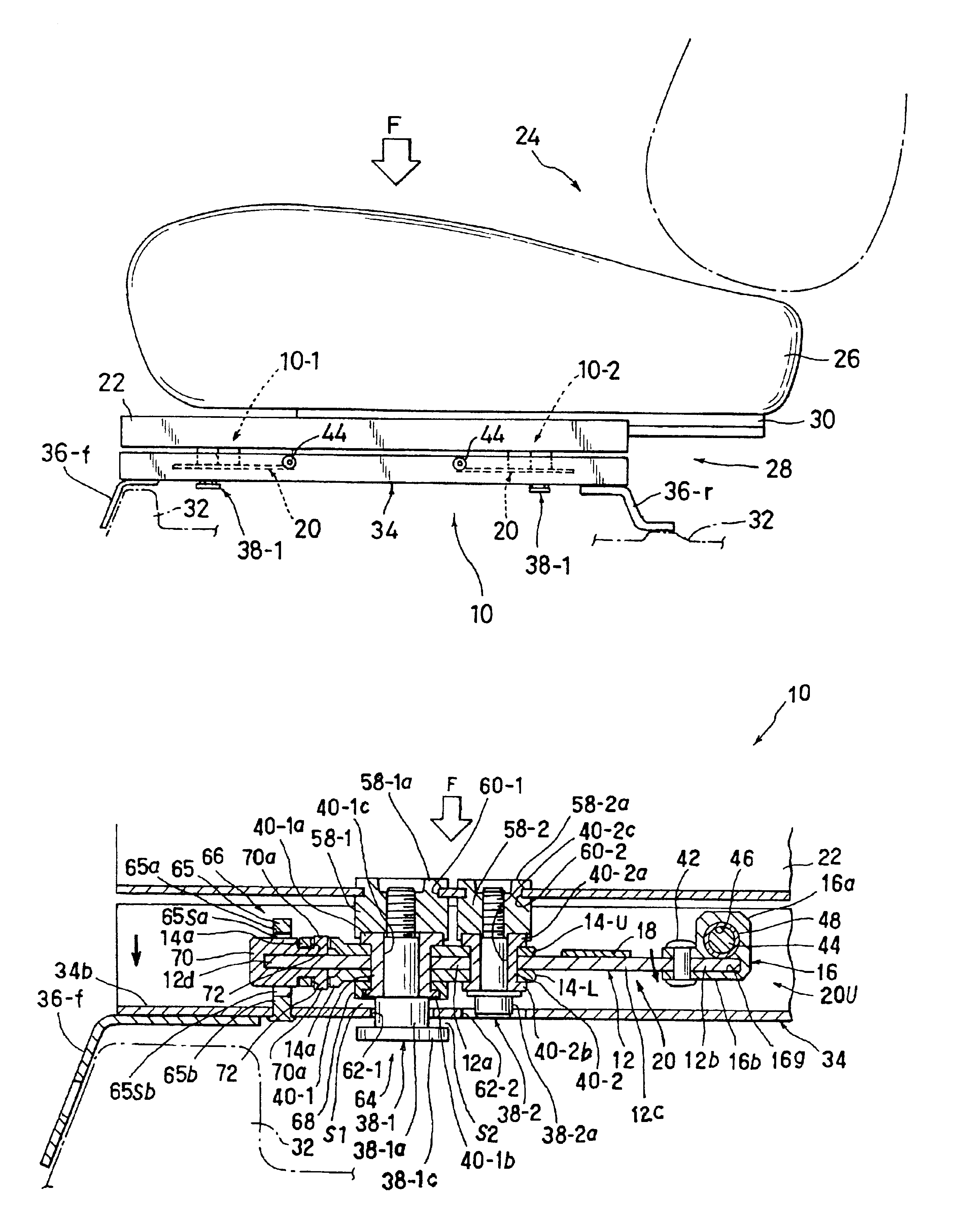
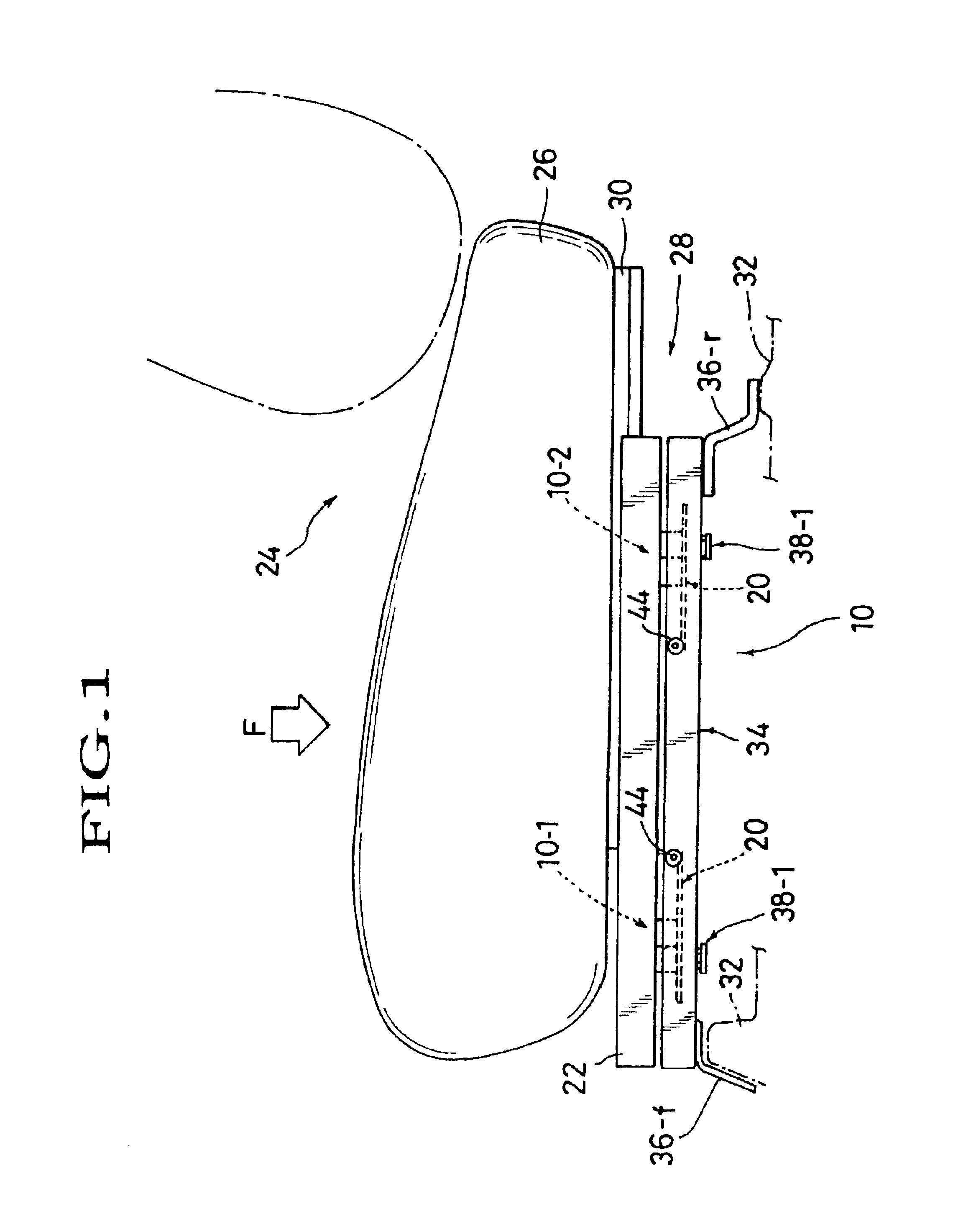
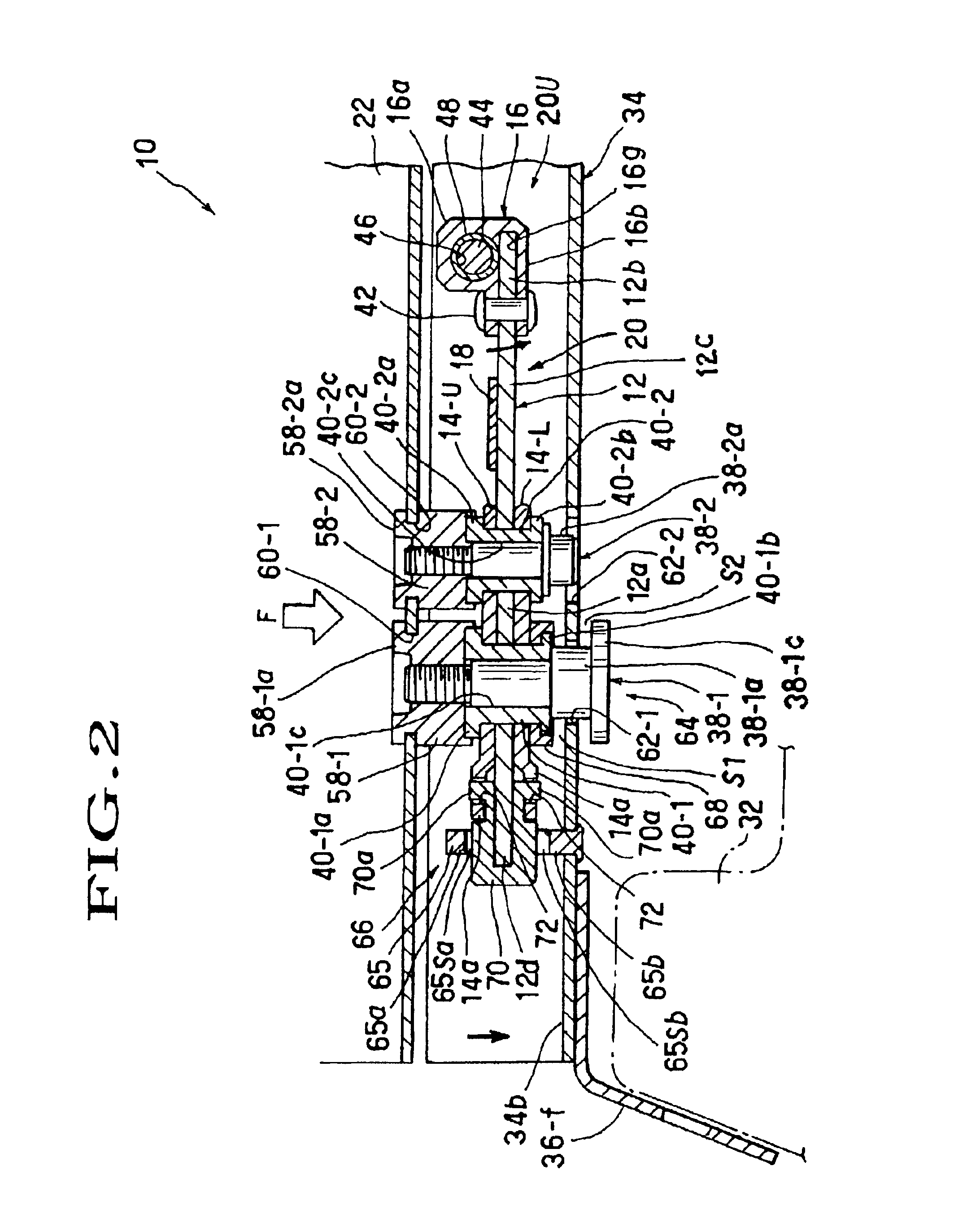
Referring to FIGS. 1 through 5, there is illustrated one preferred mode of load detection structure applicable to a vehicle seat in accordance with the present invention. Reference is first made to FIG. 1 in which the designation (10) generally represents a load detection structure provided between a slide rail device (28) and a support leg member (34) in a suspended manner.

The slide rail device (28) comprises a stationary lower rail (22) and a movable upper rail (30) slidably fitted in and along the lower rail (22). As seen from FIG. 1, the upper rail (30) is fixedly attached to a seat cushion (26) of a vehicle seat (24), whereas the lower rail (22) is securely and operatively attached via the load detection structure (10) upon the support leg member (34). Support leg member (34) has a forward vertical securing leg portion (36-f) and a backward vertical securing leg portion (36-r). As shown, those two securing leg portions (36-f) (36-r) are firmly fastened to a floor (32) of vehicl...


PUM

PropertyMeasurementUnit
elastic propertyaaaaaaaaaa
areaaaaaaaaaaa
diameteraaaaaaaaaa

Abstract

A load detection structure for seat having support leg member, which comprises: a load detection unit whose one end portion is pivotally provided in the support leg member; a limiter element for limiting vertical movement of another end portion of the load detection unit; and a stopper element for limiting further excessive vertical movement of such another end portion. The load detection unit is connected via bolts and nuts with the seat and includes: a strain plate member; a reinforcement plate member attached on a securing portion of the strain plate member through which the bolts and nuts pass; and a buffer cover member which is attached to a free end of the strain plate member, defining the afore-said another end portion of the load detection unit. A strain gauge is provided at a deflectable area of the strain plate member. The stopper element is provided at the bolt.

Description

BACKGROUND OF INVENTION1. Field of the InventionThe present invention relates to a structure allowing for detection of a load applied to a vehicle seat. In particular, the invention is directed to such load detection structure for use in a vehicle seat, in which a load detection element is mounted between the seat and support leg members in a suspended way.2. Description of Prior ArtThere have been known a passenger detection system for detecting the presence and absence of a passenger or driver in a seat of vehicle in advance before actuating or stopping the associated mechanical elements to automatically control various functions and mechanisms built in the seat.Normally, the passenger detection system employs various sensors (e.g. a pressure sensitive element) which detect the weight of a passenger on a seat and emit a signal to electronic control systems for automatic control of various mechanical elements related to the seat. Most of the sensors are of a simple structure which ...

Claims


Application Information

Patent Timeline
Patent Type & Authority Patents(United States)
IPC IPC(8): G01G19/40G01G19/414G01G19/12B60N2/90G01G19/52
CPCG01G19/4142
Inventor ISHIDA, TOSHIAKIOGASAWARA, HIROMITSU
Owner TACHI S CO LTD
Why Eureka
Try Eureka