Electrophoretic display device and process for production thereof

a display device and display technology, applied in the field of electrotrophoretic display devices, can solve the problems of low luminance of light sources, visual load on human eyes, and difficulty in recognizing characters

Inactive Publication Date: 2004-06-15
CANON KK
View PDF8 Cites 119 Cited by
  • Summary
  • Abstract
  • Description
  • Claims
  • Application Information

AI Technical Summary

Problems solved by technology

However, such liquid crystal display devices are still accompanied with problems of visual load on human eyes, such as difficulty of recognizing characters on display depending on a viewing angle or due to reflection light, and flickering and low luminance of light source.
Further, because of necessity of alignment control of liquid crystal molecules and accurate control of liquid crystal cell gap, it is difficult to also satisfy a flexibility of the device.
However, a conventional electrophoretic display device is accompanied with the following problems.
A first problem is encountered at the time of injecting the electrophoretic dispersion liquid between the substrates in the process for producing the electrophoretic display device.
Further, in the case of injecting the electrophoretic dispersion liquid from an edge of the device toward the edge on the opposite side, the dispersion medium can be easily transferred but the electrophoretic particles are liable to be caught at the spacer and partitioning walls, so that the electrophoretic particle concentration is liable to be high near the injection port and lowered at points leaving away from the injection port, thus adversely affecting the display uniformity.
According to this process, a uniform concentration of electrophoretic particles over the planar extension of the device can be realized, but a problem of entrainment of air bubbles is liable to occur at the time of bonding the upper substrate.
A second problem is encountered as a difficulty of realizing a device showing paper-like flexibility.
This is because an electrophoretic. display device is composed of two substrates so that it is difficult to absorb a difference between an inner circumference and an outer circumference caused when the device is flexurally deformed even if the two substrates are composed of flexible materials.
Thus, the flexured device is liable to result in a stiff touch.
A third problem is liable to be encountered when a flexible device is flexurally deformed.

Method used


Image

  • Electrophoretic display device and process for production thereof
  • Electrophoretic display device and process for production thereof
  • Electrophoretic display device and process for production thereof

Examples


example 2

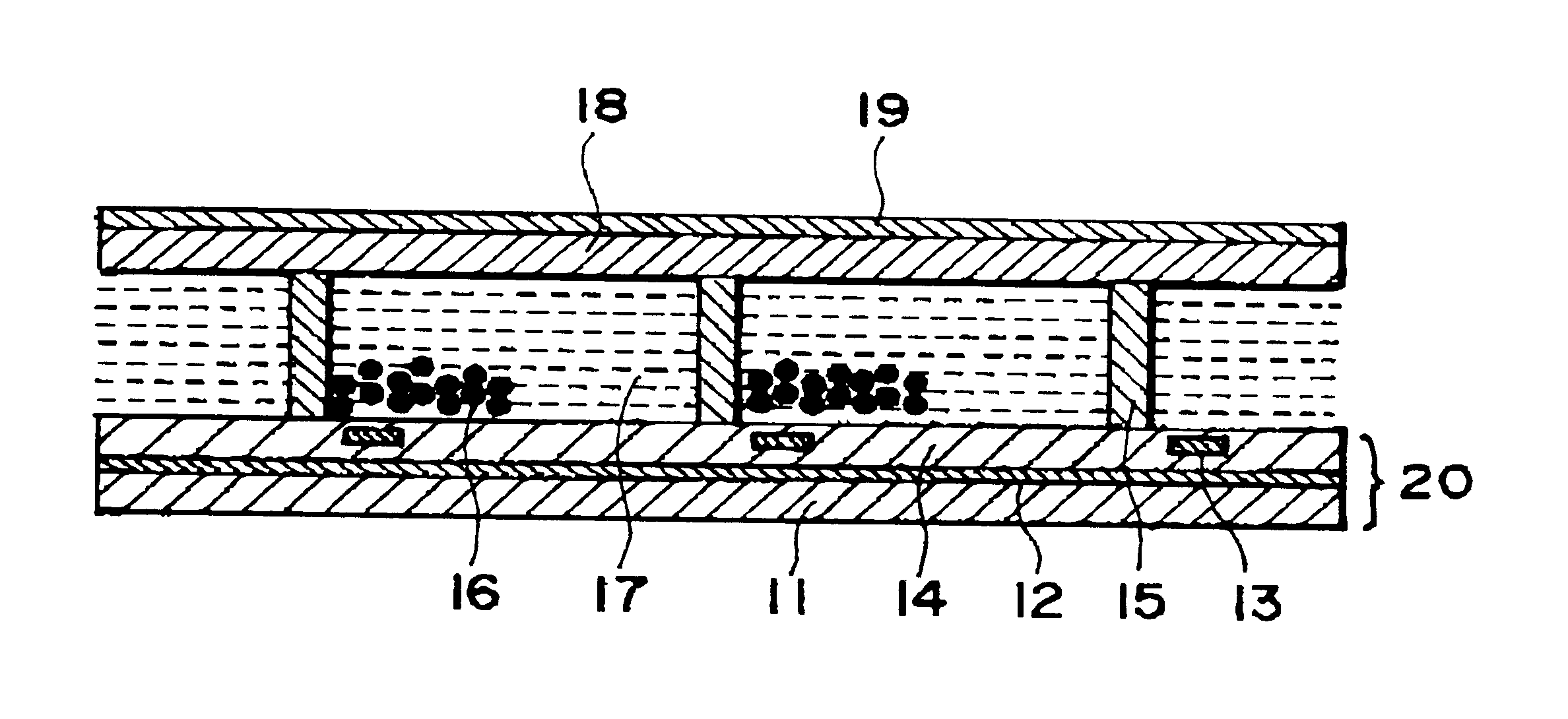
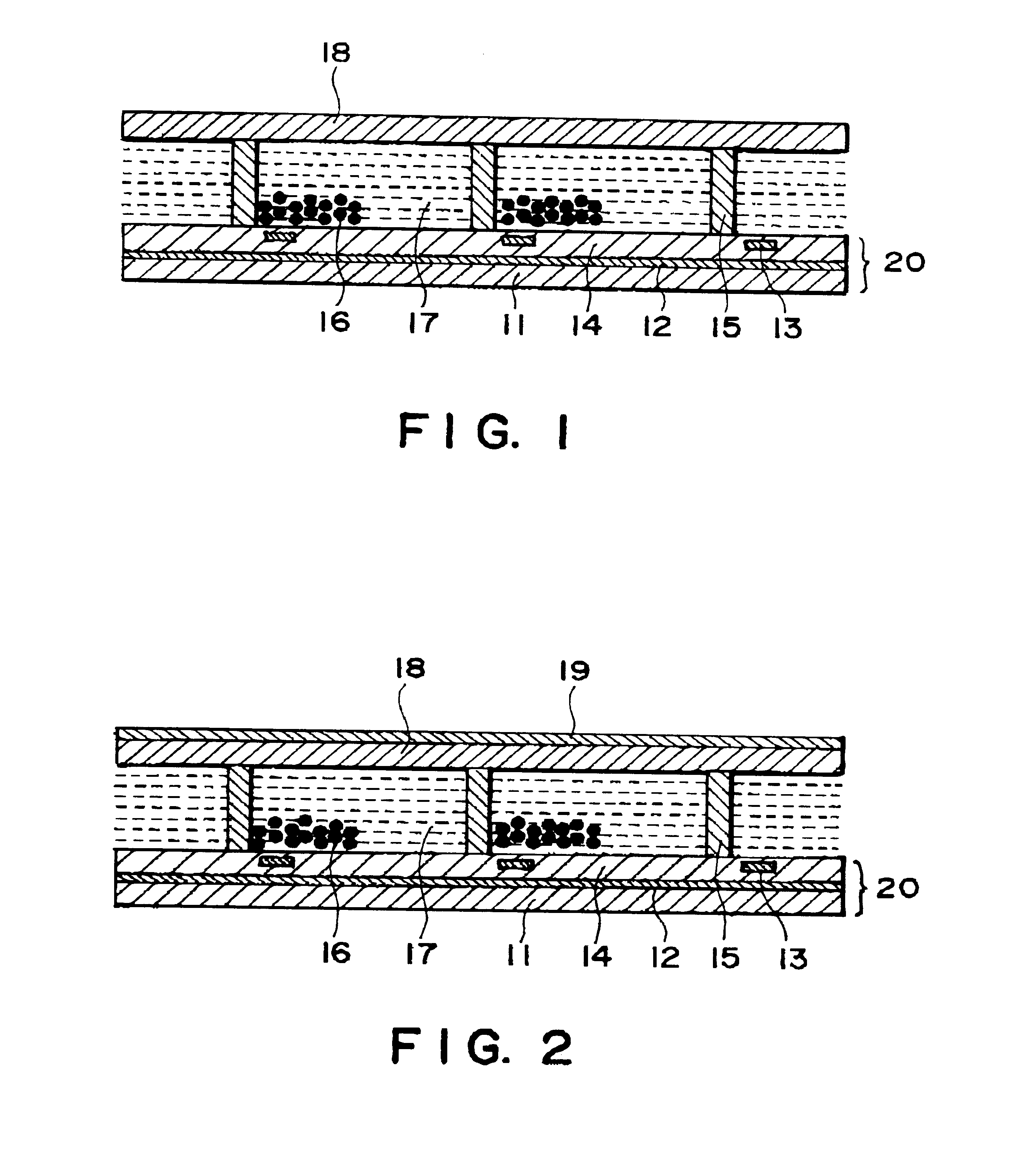
The process of Example 1 was repeated up to the distributive injection of the electrophoretic dispersion liquid except for using a UV-curable resin comprising novolak resin ("PMER", made by Tokyo Ohka Kogyo K.K.).

Then, over the dispersion liquid distributed to the display sections, a mixture liquid comprising 60 parts of styrene-isoprene block polymer, 40 parts of maleic acid ester and 1 part of benzoyl ether, was uniformly applied by a microsprayer (made by Nordson Corp.), and then uniformly exposed to ultraviolet rays, followed by drying at 120.degree. C., to form a 100 -m-thick transparent ceiling sheet.

The electrophoretic dispersion liquid contained in the resultant electrophoretic display device exhibited a uniformly distributed concentration of electrophoretic particles over the extension of the device.

It was confirmed that the device operated in a similar manner as in Example 1.

example 3

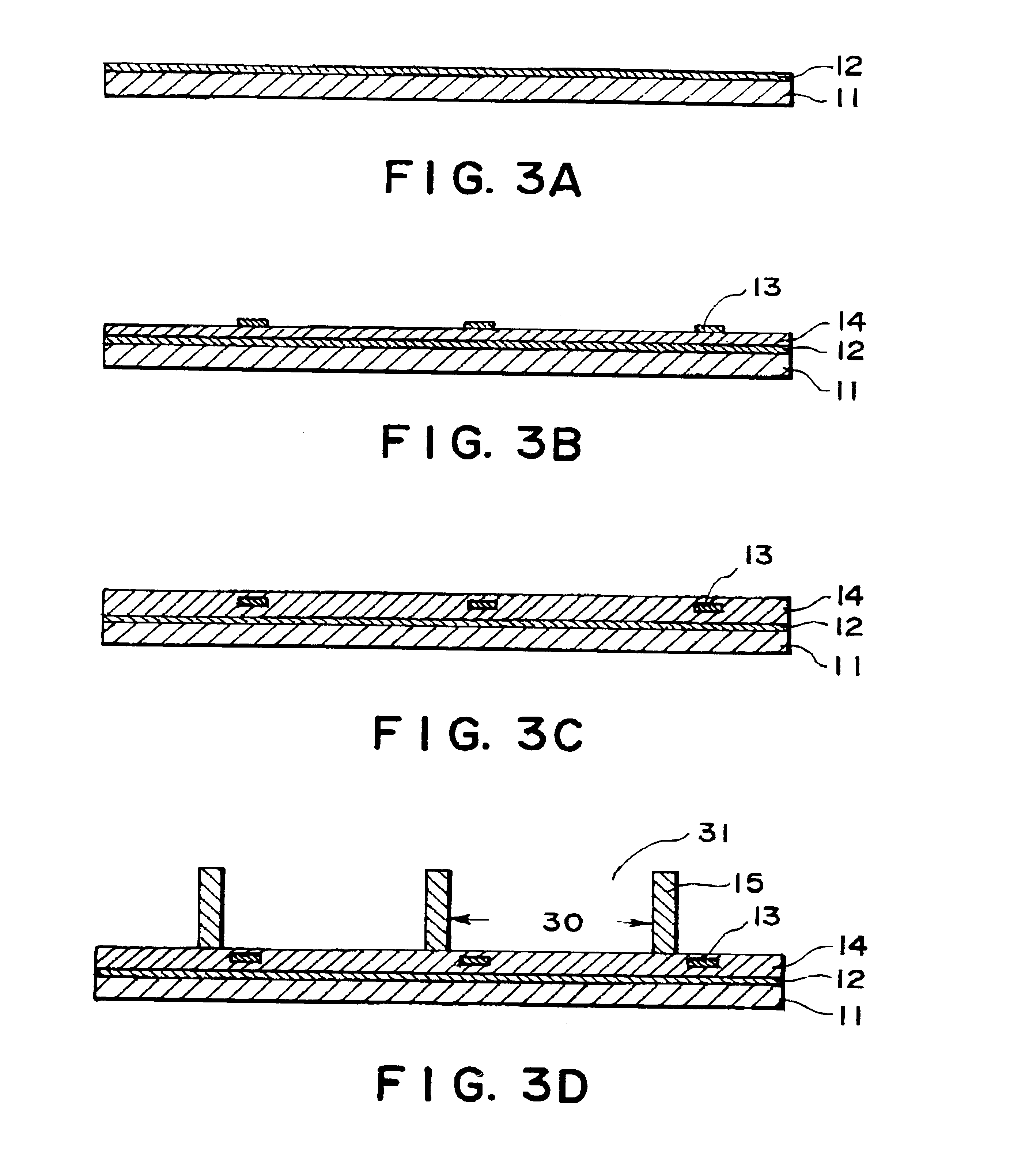
The process of Example 2 was repeated up to the distributive injection of the electrophoretic dispersion liquid except for forming the insulating layer over the aluminum electrodes (second electrodes 13) with a 100:30 (by weight) mixture of alumina particles and acrylic resin ("OPTMER"), thus providing a 2 .mu.m-thick insulating and reflecting layer.

Then, over the dispersion liquid distributed to the display sections, a mixture liquid comprising 65 parts of terminal hydrogenated polybutadiene, 40 parts of fumaric acid ester and 1 part of benzyl ketal, was uniformly applied by a microsprayer (made by Nordson Corp.) and then uniformly exposed to ultraviolet rays to form a 100 .mu.m-thick transparent ceiling sheet, thereby completing an electrophoretic display device having a sectional structure similarly as shown in FIG. 1.

The electrophoretic dispersion liquid contained in the resultant electrophoretic display device exhibited a uniformly distributed concentration of electrophoretic p...


PUM

PropertyMeasurementUnit
thicknessaaaaaaaaaa
thicknessaaaaaaaaaa
widthaaaaaaaaaa

Abstract

A pliable electrophoretic display device having a deformation-resistant memory characteristic is provided by covering a plurality of partitioning walls defining display sections containing a dispersion liquid with electrophoretic particle dispersed therein with an expandable ceiling sheet. Such a ceiling sheet is formed by applying a hardenable precursor liquid, which is immiscible with the dispersion liquid, over the partitioning walls containing the dispersion liquid and hardening the precursor liquid in situ by exposure to light, heat or by drying.

Description

FIELD OF THE INVENTION AND RELATED ARTThe present invention relates to an electrophoretic display device and a process for production thereof.Along with development of data processing apparatus and devices in recent years, there is an increasing demand for so-called "paper-like display" which is rewritable electronic paper satisfying the convenience of paper medium and electronic medium function for a portable personal computer. A display device used for such a paper-like display should require a small power consumption, be thin and have a flexibility like paper durable against flexure. One sheet or plural sheets of such display devices are used as a paper-like display.Display devices in compliance with such a demand have been a subject of extensive research and development. Among these, a liquid crystal display device wherein an alignment of liquid crystal molecules is electrically controlled to change optical characteristics has been extensively developed and commercialized as a d...

Claims


Application Information

Patent Timeline
Patent Type & Authority Patents(United States)
IPC IPC(8): G02F1/01G02F1/167G02F1/13G02F1/1341G02F1/1679
CPCG02F1/167G02F1/1341G02F1/1679
Inventor NAKANISHI, MASAHIRO
Owner CANON KK
Why Eureka
Try Eureka