Process for producing nano-powders and powders of nano-particle loose aggregate

a nano-particle and loose aggregate technology, applied in the field of ultra fine powder preparation, can solve the problems of difficult to eliminate hard agglomeration among particulates, difficult to control particle diameter, difficult to obtain very small particle diameter,

Inactive Publication Date: 2007-07-03
UNIV OF SCI & TECH LIAONING
View PDF10 Cites 36 Cited by
  • Summary
  • Abstract
  • Description
  • Claims
  • Application Information

AI Technical Summary

Problems solved by technology

Although this technology for preparing nano-particles has the advantage of simple operation, low cost and high yield, it has three generally recognized disadvantages as follows: (1) it is difficult to control particle diameter; (2) it is difficult to obtain very small particle diameter; (3) it is difficult to eliminate hard agglomeration among particulates.
The origin of the drawbacks of the pot technology comes from the too long feeding time for one of the reactant solution and from the mixing of the reaction, product and precipitate formed at different stages of time while stirring.
As mentioned above, these are the causes of the above-mentioned three drawbacks of the large pot technology in preparing nano-powder.
The drawbacks of that method are: (1) reactant solutions are injected in a pulse mode and the mixing process is not continuous, thus the process is not favorable for large-scale continuous industrial production, and since carrier fluid must be used, the manufacturing process gets complex, it not only consumes carrier fluid but also needs a separation treatment for the carrier fluid and etc. and thus increases the production cost; (2) the method does not take any effective measures to reinforce and to adjust the mechanical mixing efficiencies of the two reactant solutions, therefore, it is impossible to effectively control the mechanical mixing efficiency of the reactant solutions.
However, there were still some drawbacks in the method of super gravity rotating packed bed.
Due to the high compactness of the fillers such as steel wire net and in the packed bed, what obtained by the solution was not the action of stirring and shear.
The mechanical mixing intensity and the adjusting sensitivity of such kind of mixing were not high enough and thus the performance of the preparation of nano-powder was not ideal.

Method used


Image

  • Process for producing nano-powders and powders of nano-particle loose aggregate
  • Process for producing nano-powders and powders of nano-particle loose aggregate
  • Process for producing nano-powders and powders of nano-particle loose aggregate

Examples


example 1

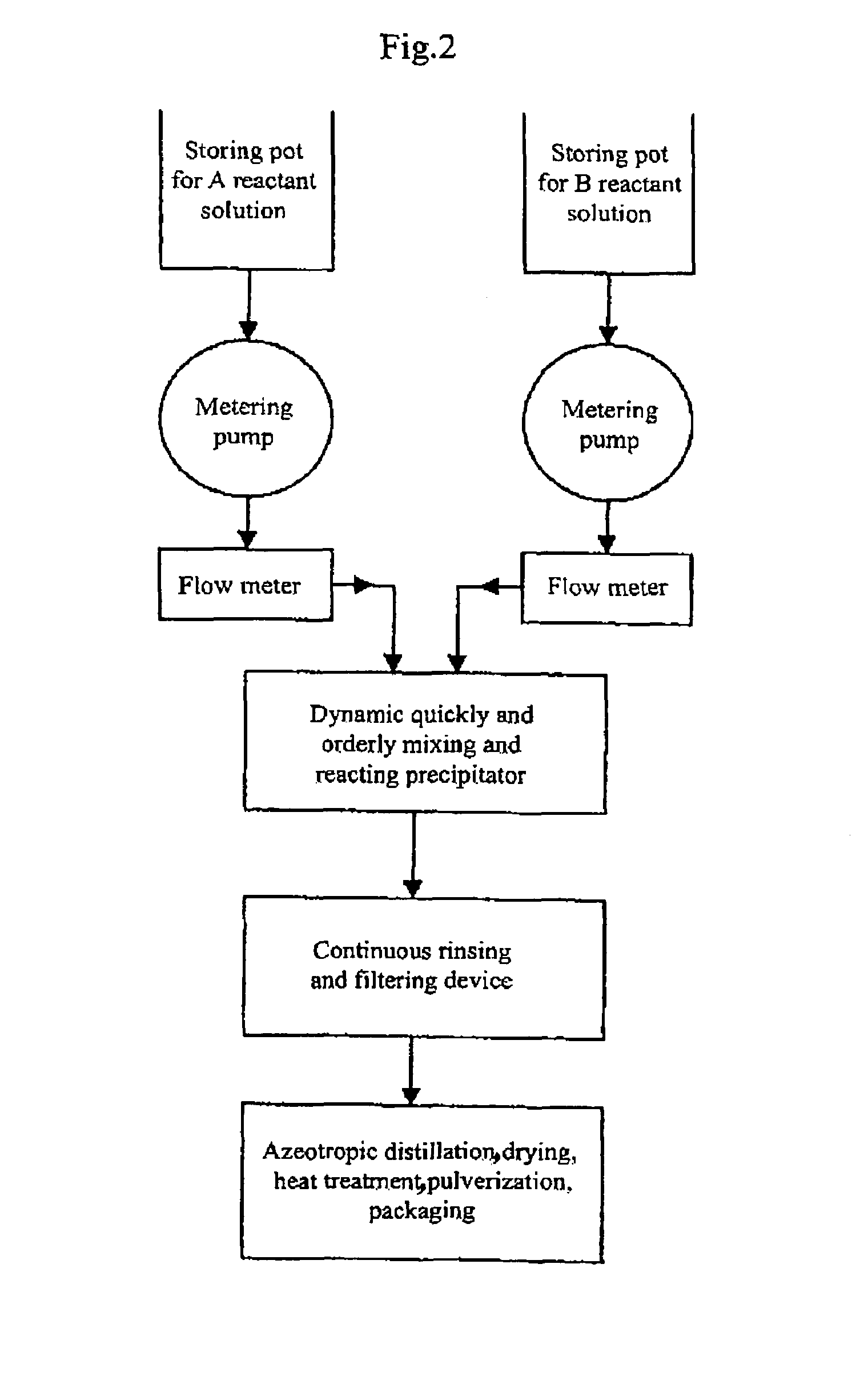
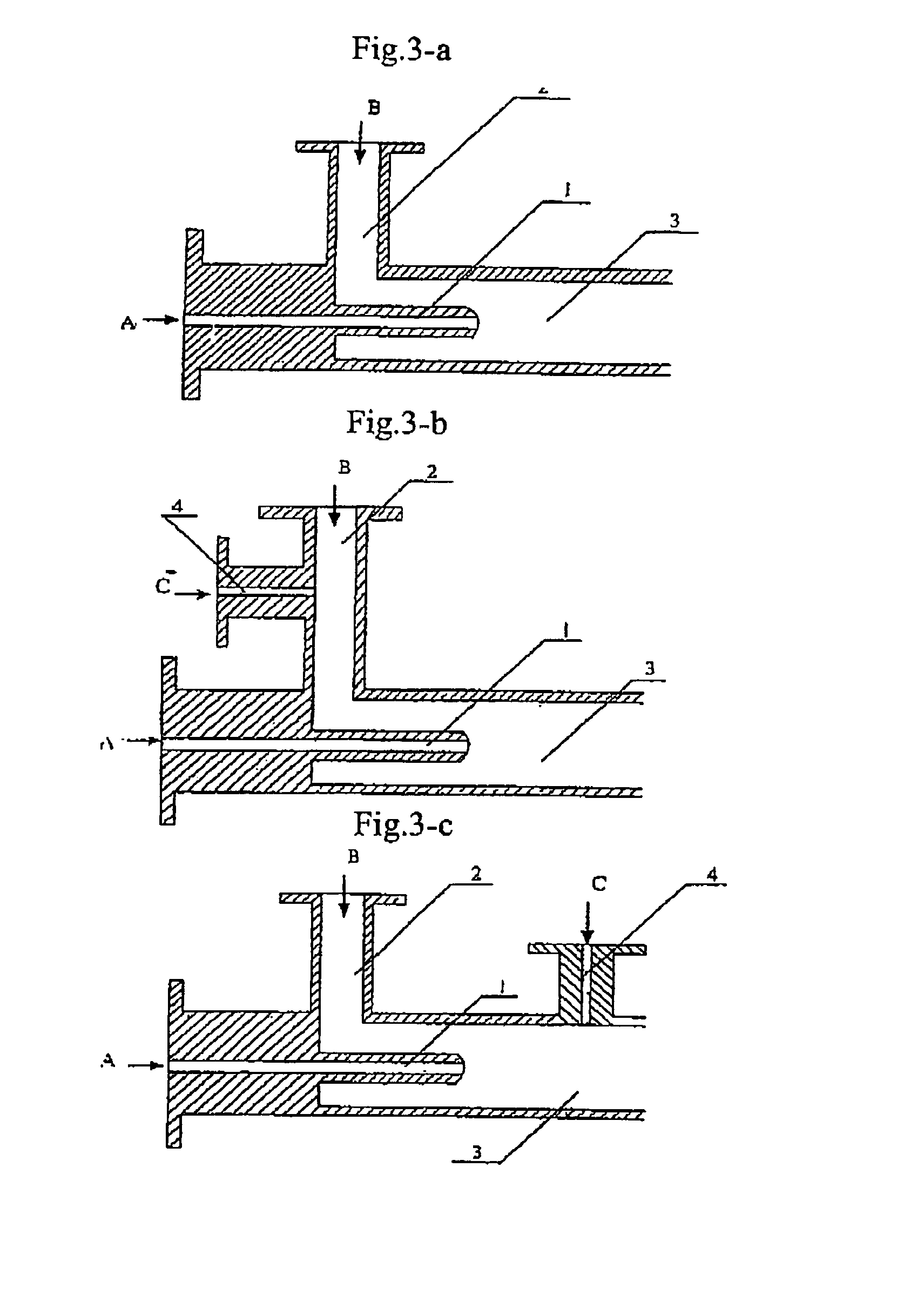
[0091]773.4 g of zirconium oxide chloride ZrOCl2.8H2O (molecular weight=322.25 and purity≧99%) was weighed and 3000 ml of 0.8 mol / L ZrOCl2 aqueous solution was prepared from the zirconium oxide chloride, called solution A. Secondly-distillated water and then 2100 ml of ethanol (95%) as a dispersing agent were added to 375 ml of ammonia having a NH3 concentration of 25% to produce 3000 ml of an aqueous solution called solution B. Solution A and solution B were mixed in a tubular coaxial ejection mixing reactor as shown in FIG. 3-a and reacted with each other to form precipitate at room temperature of 20° C. as illustrated in the process flow chart shown in FIG. 2. The pH value of the resultant was adjusted to be 7–8 by the addition of ammonia. The tubular coaxial ejection mixing reactor had an inner diameter of 10 mm and an inner diameter of spray hole of 1 mm. The flows of solution A and solution B are both 200 L / h. The pressure at the spray inlet for solution A was 100 kg / cm2. The ...

example 2

[0092]333.6 g of ZnCl2 was weighed and secondly-distillated water was added to produce 3000 ml of 0.8 mol / L ZnCl2 aqueous solution called solution A at a temperature of 70° C. 900 ml ethanol (95%) as a dispersing agent was added to 375 ml of ammonia water (25%) to produce 3000 ml of 0.8 mol / L NH3 aqueous solution in ethanol called solution B at a temperature of 30° C. Solution A and solution B were mixed in a tubular coaxial ejection mixing reactor as shown in FIG. 3-a and reacted with each other to form precipitate as illustrated in the process flow chart shown in FIG. 2. The pH value of the resultant was adjusted to be 7–8 by the addition of ammonia. The tubular coaxial ejection mixing reactor had an inner diameter of 10 mm and an inner diameter of spray hole of 1 mm. The flows of solution A and solution B are both 150 L / h. The pressure at the spray inlet for solution A was 90 kg / cm2. The slurry containing the resulting precipitate was fed into a continuously-running equipment for...

example 3

[0093]441.6 g of BaCI2 was weighed and secondly-distillated water and 900 ml ethanol were added to produce 3000 ml of 0.6 mol / L BaCl2 aqueous solution called solution A at a temperature of 20° C. 156.6 g of NH4HCO3 was weighed and secondly-distillated water, 180 ml of ammonia water (25%) and 1200 ml of ethanol (95%) as a dispersing agent were added to produce a 3000 ml solution called solution B at a temperature of 20° C. Solution A and solution B were mixed in a tubular coaxial ejection mixing reactor as shown in FIG. 3-a and reacted with each other to form precipitate as illustrated in the process flow chart shown in FIG. 2. The pH value of the resultant was adjusted to be 7–8 by the addition of ammonia water. The tubular coaxial ejection mixing reactor had an inner diameter of 10 mm and an inner diameter of spray hole of 1 mm. The flows of solution A and solution B are both 160 L / h. The pressure at the spray inlet for solution A was 100 kg / cm2. The slurry containing the resulting...


PUM

PropertyMeasurementUnit
temperatureaaaaaaaaaa
residence timeaaaaaaaaaa

Abstract

The present invention discloses a process for producing nano-powders and powders of nano-particle loose aggregate, which includes: (a) providing at least two reactant solutions A and B capable of rapidly reacting to form deposits; (b) supplying the at least two reactant solutions A and B at least at the reaction temperature into a mixing and reaction precipitator respectively, in which mixing reaction and precipitation are continuously carried out in sequence, the mixing and reaction precipitator being selected from at least one of a tubular ejection mixing reactor, a tubular static mixing reactor and an atomization mixing reactor; and (c) treating the deposit-containing slurry continuously discharged from the mixing reaction precipitator.

Description

RELATED APLLICATIONS[0001]This application represents the U.S. National Phase of International Application No. PCT / CN02 / 00521 filed Jul. 26, 2002, designating the United States of America and published in Chinese, which claims the benefit of priority of Chinese Patent application No. 01127978.8 filed Jul. 27, 2001.FIELD OF THE INVENTION[0002]The present invention relates to a method of preparation for ultra fine powders. More specifically, it relates to a method of preparation for nanometer grade powders (hereinafter called as nano-powders) and powder of loose aggregates of the nanometer grade particles (hereinafter it is called as nano-particle loose aggregate powder, and the nanometer grade particle as nano-particle). Especially, it relates to a method utilizing liquid phase chemical reaction to form a precipitate to prepare nano-powders and nano-particle loose aggregate powders.BACKGROUND OF THE INVENTION[0003]It is well known that particulates of metals or metal oxides with size...

Claims


Application Information

Patent Timeline
Patent Type & Authority Patents(United States)
IPC IPC(8): C01G1/00B01F3/08B01J19/00C01F11/18C01G1/02C01G9/00C01G25/02
CPCB82Y30/00C01G1/02C01P2004/03C01P2004/52C01P2004/64C01P2006/22Y10S977/773Y10S977/775Y10S977/777B82B3/00B82Y40/00
Inventor ZHOU, YINGYANGAO, SHOUSHANWANG, KAIMINGWEN, CHUANGENGLI, XIAOQI
Owner UNIV OF SCI & TECH LIAONING
Why Eureka
Try Eureka