Method of transmitting and receiving compressed television signals

a television signal and compressed technology, applied in the field of compressed television signal transmission, can solve the problem that the server cannot determine the stream position exactly

Inactive Publication Date: 2004-06-15
KONINKLIJKE PHILIPS ELECTRONICS NV
View PDF7 Cites 41 Cited by
  • Summary
  • Abstract
  • Description
  • Claims
  • Application Information

AI Technical Summary

Benefits of technology

The invention concentrates on two trick-modes, namely: `pause / continue` and `slow motion`. The required functionality for `pause and continue` is that a user can pause the display at any point in time and can continue flawlessly afterward. Preferably, interruption takes effect immediately e.g. at the frame / field which is currently displayed and continuation should occur at the next frame without any missing or duplicated frames. `Pause and continue` involves the transmission of `Pause` and `Resume` commands from the decoder to the server to stop and continue the stream. The required functionality for `slow motion` is that a user can visualize the stream at a speed lower than the normal playback speed. The decoder should be able to switch between the slow motion mode and normal playback mode. The switch should take effect immediately without any missing or duplicated frames. `Slow motion` also involves the transmission of `Pause` and `Resume` messages from the decoder to the server to stop and start the stream.

Problems solved by technology

Normally, the server cannot exactly determine the stream position at the time the pause was effected at the decoder due to the latency in the communication between decoder and server.

Method used


Image

  • Method of transmitting and receiving compressed television signals
  • Method of transmitting and receiving compressed television signals
  • Method of transmitting and receiving compressed television signals

Examples


Embodiment Construction

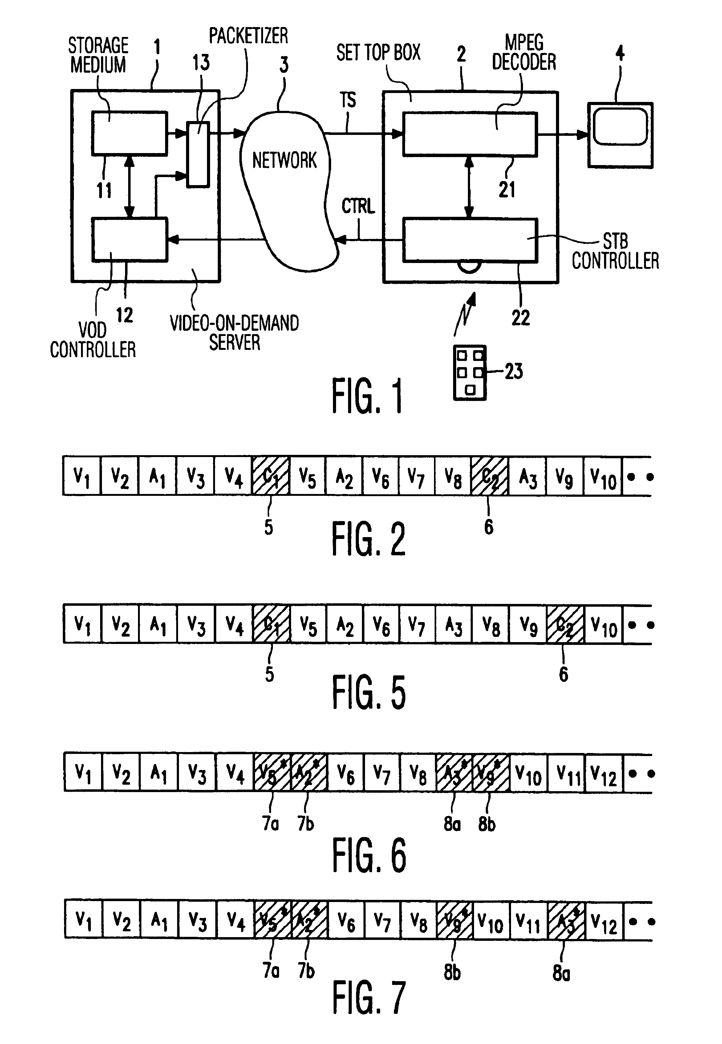
FIG. 1 shows a system comprising a Video-On-Demand (VOD) server 1 and a set top box (STB) 2 connected via a network 3. The VOD-server comprises a storage medium 11 and a VOD-controller 12. The STB comprises an MPEG decoder 21, an STB-controller 22 and a (remote) control unit 23, and is connected to a reproduction device 4. User commands from remote control unit 23 are applied to STB-controller 22 and, as far as they require actions to be taken by the server, transmitted to the VOD-controller 12 via the network 3 as a control signal CTRL. A selected television program is transmitted from the server 1 to STB 2 in the form of an MPEG Transport Stream TS.

A plurality of television programs is stored on storage medium 11 which is usually an array of hard disks. From the STB point of view, the server behaves as a remote video recorder. The stored television programs can be played back at various speeds, paused and resumed. More particularly, the server can be instructed to playback the pro...


PUM


Abstract

The invention relates to the transmission of MPEG encoded television signals from a Video-On-Demand server (1) to a receiver (2) via a network (3). Non-linear playback functions such as 'pause' and 'resume' require a very accurate control of the bit stream, taking account of typical network aspects such as network latency and remultiplexing. In order to allow the receiver to flawlessly resume signal reproduction after a pause, position labels (p; 5,6; 7a,7b,8a,8b) are inserted into the bit stream at positions where the server can resume transmission of the signal after an interruption. Upon a pause request, the decoder initially continues the reproduction until such a position label is detected. The subsequent bits delivered by the network are ignored, i.e. they are thrown away. Upon a request to resume reproduction, the receiver requests the server to retransmit the signal starting at the detected position.

Description

The invention relates to methods of transmitting and receiving compressed television signals. The invention also relates to arrangements for carrying out said methods, more particularly, arrangements such as video-on-demand servers for transmitting, and set top boxes for receiving, MPEG compressed audio and video signals.The so-called "Transport stream" and "Program Stream" as defined within the MPEG-2 standard provide a standardized mechanism for the transmission and storage of MPEG compressed audio and video (A / V) information. Both streams contain time stamps to synchronize the decoding and presentation of the conveyed audio and video information while ensuring that data buffers in the decoders do not overflow or underflow during linear playback. In addition, these time stamps are used for the correct delivery of the streams themselves. The MPEG Transport Stream is tailored to the communication or the storage of one or more programs of digital data in environments in which signifi...

Claims


Application Information

Patent Timeline
Patent Type & Authority Patents(United States)
IPC IPC(8): G06T9/00H04N7/173H04N7/26H04N21/2387H04N21/472H04N21/845
CPCG06T9/007H04N7/17318H04N21/2387H04N21/47202H04N21/8455H04N21/6375
Inventor HUIZER, CORNELIS M.KAREL, LUCAS M. W. M.BOSVELD, FRANKDE VISSER, PIETER JAN
Owner KONINKLIJKE PHILIPS ELECTRONICS NV
Why Eureka
Try Eureka