Three phase converter fed motor having a shielding device to eliminate capacitive current in stator slots

a three-phase converter and shielding device technology, applied in the field of three-phase motors, can solve the problems of bearing damage, bearing current through bearings and housings, and bearing damage in modern converter-fed three-phase motors

Inactive Publication Date: 2004-06-29
MANNESMANN AG
View PDF3 Cites 18 Cited by
  • Summary
  • Abstract
  • Description
  • Claims
  • Application Information

AI Technical Summary

Problems solved by technology

Bearing damage is on the rise in modern converter-fed three-phase motors due to the high switching speed of IGBT converters.
This bearing damage is caused by high-frequency bearing currents flowing through the shaft, bearing and laminated stator core.
The bearing currents are induced because a high voltage gradient of the

Method used


Image

  • Three phase converter fed motor having a shielding device to eliminate capacitive current in stator slots
  • Three phase converter fed motor having a shielding device to eliminate capacitive current in stator slots
  • Three phase converter fed motor having a shielding device to eliminate capacitive current in stator slots

Examples


Embodiment Construction

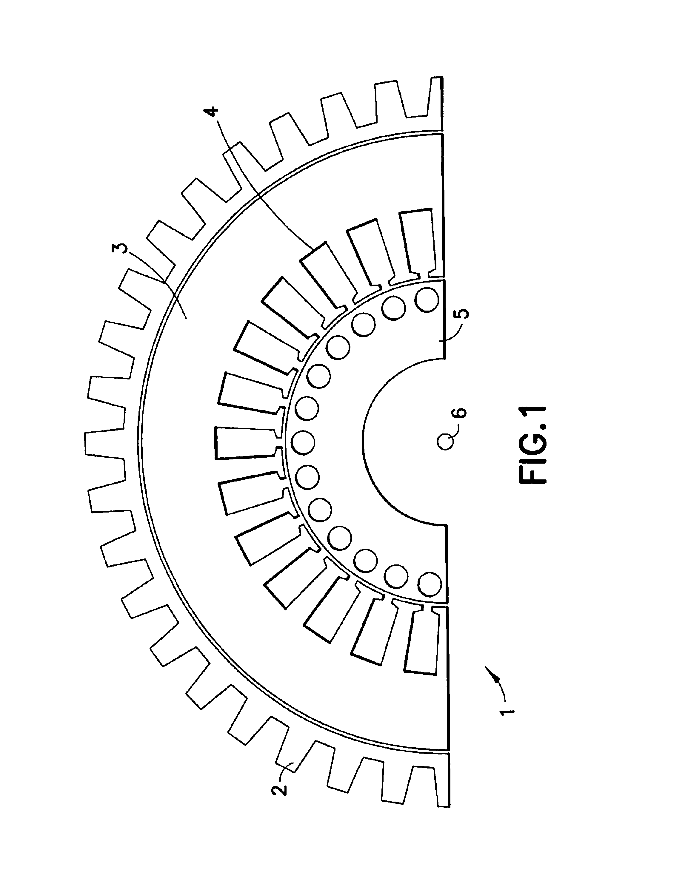
FIG. 1 shows, schematically, a section through a three-phase motor 1 having a housing with cooling ribs 2, a stator laminate 3 with (as a rule 36) stator slots 4, a rotor laminate 5 and a shaft 6 to be driven.

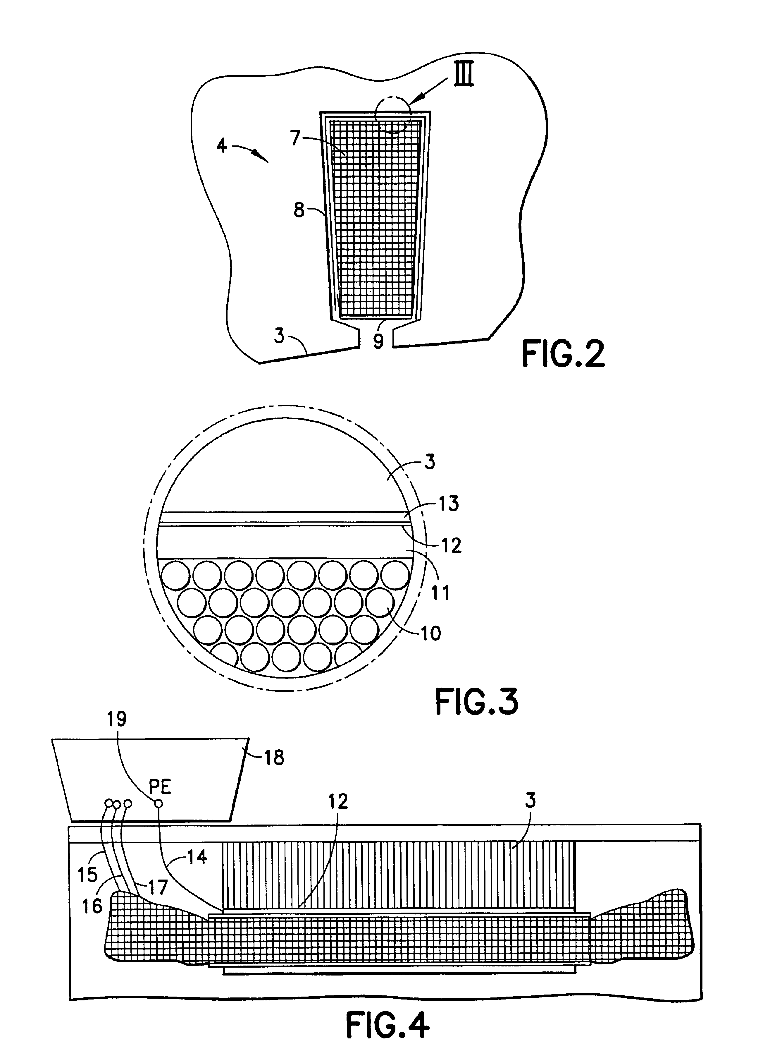
FIG. 2 shows copper windings 7, slot insulation 8, a stator laminate 3 and a slot cover 9 for a stator slot 4. FIG. 3 shows an enlargement of the detail shown in the circle in FIG. 2, with copper wires 10 of the winding 7, conventional slot insulation 11 and a shield 12 according to the present invention between the windings 7 of copper wires 10 and the stator laminate 3. Conventional slot insulation 11 is provided between the electrically conductive shield 12 and the winding 7 of copper wires 10. Further insulation by means of the insulating layer 13 is provided between the shield 12 and the stator laminate 3. The shield 12 is thus located between the winding 7 of copper wires 10 and the stator laminate, but is insulated from both.

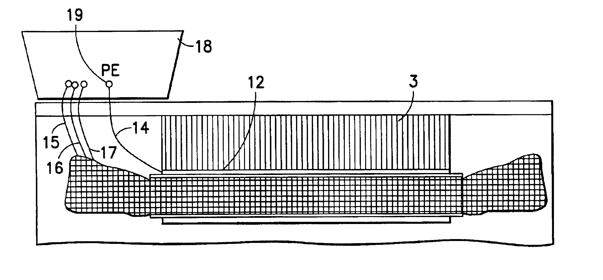
As FIG. 4 shows in a partial longitudinal sect...


PUM


Abstract

A device for preventing bearing damage from currents through a three-phase motor is provided, including a shield for winding and copper wire within each stator slot of a motor. The shield includes an electrically conductive layer which is insulated from the winding and from the laminated stator core of the three-phase motor. The conductive layer is grounded or conductively connected to the laminated stator core of the three-phase motor on only that side on which the three-phase current is fed to the winding of the motor.

Description

1. Field of the InventionThe present invention relates to a three-phase motor which can be fed from a converter. More particularly, the present invention includes a shielding device that eliminates capacitive current in the stator slots so as to prevent a current circuit in the laminated core of the motor and avoid inducing voltage in the motor shaft.2. Description of the Related ArtBearing damage is on the rise in modern converter-fed three-phase motors due to the high switching speed of IGBT converters. This bearing damage is caused by high-frequency bearing currents flowing through the shaft, bearing and laminated stator core. The bearing currents are induced because a high voltage gradient of the feed voltage with respect to ground induces a voltage in the motor shaft, which results in bearing currents through the bearings and the housing. As remedial measures to prevent these bearing currents, the person skilled in the art is familiar with insulated bearings composed of ceramic...

Claims


Application Information

Patent Timeline
IPC IPC(8): H02K3/34H02K3/32H02K11/00H02K11/01
CPCH02K3/345H02K11/0005H02K11/014
Inventor SCHUREN, VOLKER
Owner MANNESMANN AG
Why Eureka
Try Eureka