Impulse radio receiver and method for finding angular offset of an impulse radio transmitter

a radio transmitter and impulse technology, applied in direction finders using radio waves, amplitude demodulation, instruments, etc., can solve the problems of large transmit power, multiple radios, and inability to determine the position of opposing radios

Inactive Publication Date: 2004-07-06
HUMATICS CORP
View PDF3 Cites 139 Cited by
  • Summary
  • Abstract
  • Description
  • Claims
  • Application Information

AI Technical Summary

Problems solved by technology

A limitation common among these inventions is the requirement for multiple radios to determine the position of another.
However, without relative angle information or distance information from another source, the position of the opposing radio cannot be determined.
However, baseband systems, compared to impulse systems, use much greater transmit power and are not very well channelized rendering such systems very susceptible to interference.
Thus, they tend to be impractical for applications other than in electromagnetically clear space or in areas in which interference with other systems is not a concern.

Method used


Image

  • Impulse radio receiver and method for finding angular offset of an impulse radio transmitter
  • Impulse radio receiver and method for finding angular offset of an impulse radio transmitter
  • Impulse radio receiver and method for finding angular offset of an impulse radio transmitter

Examples


Embodiment Construction

Overview of the Invention

The present invention will now be described more fully in detail with reference to the accompanying drawings, in which the preferred embodiments of the invention are shown. This invention should not, however, be construed as limited to the embodiments set forth herein; rather, they are provided so that this disclosure will be thorough and complete and will fully convey the scope of the invention to those skilled in art. Like numbers refer to like elements throughout.

Impulse Radio Technology Overview

Recent advances in communications technology have enabled ultra wideband technology (UWB) or impulse radio communications systems "impulse radio". To better understand the benefits of impulse radio to the present invention, the following review of impulse radio follows. Impulse radio has been described in a series of patents, including U.S. Pat. No. 4,641,317 (issued Feb. 3, 1987), U.S. Pat. No. 4,813,057 (issued Mar. 14, 1989), U.S. Pat. No. 4,979,186 (issued Dec...


PUM


Abstract

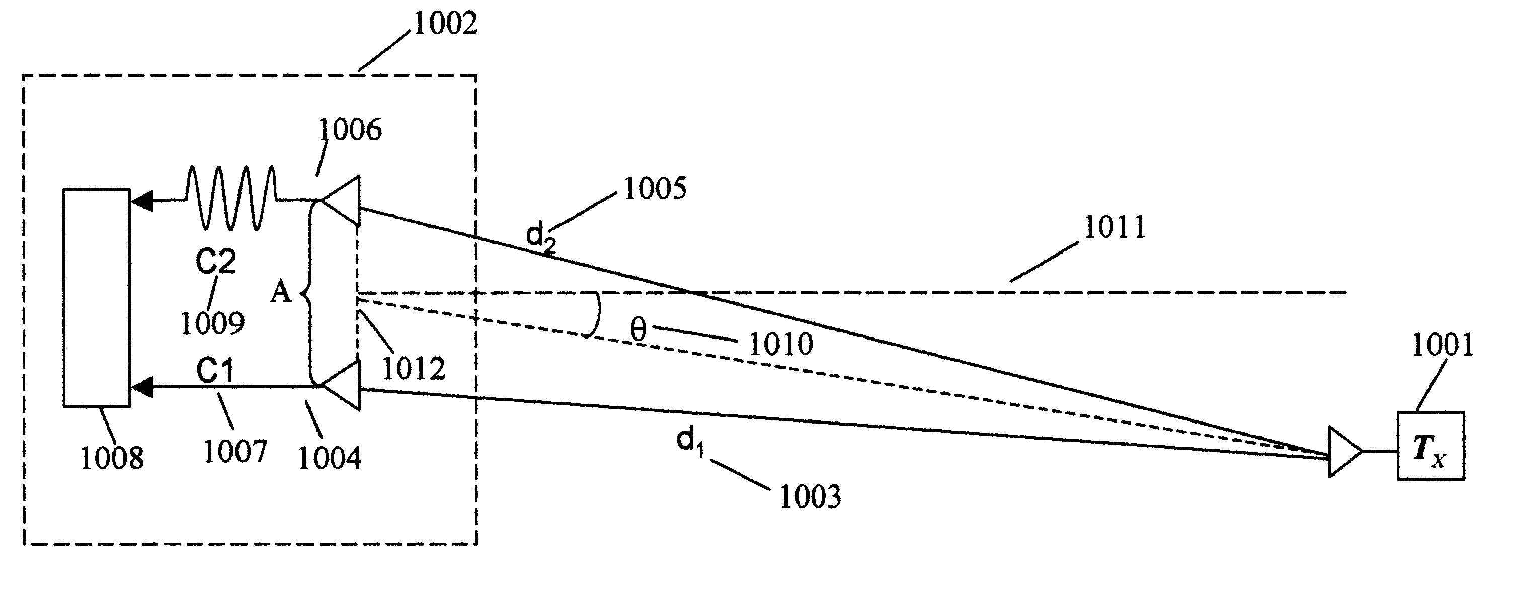
A system and method for determining angular offset of an impulse radio transmitter using an impulse radio receiver coupled to two antennae. The antennae are separated by some known distance, and, in one embodiment, one antennae is coupled to the radio with cable delay. Impulse signals from the antennae are measured to determine the time difference of arrival of one such signal received by one antenna compared to that of the other antenna. Time differential is measured by autocorrelation of the entire impulse radio scan period, by detecting the leading edges of both incoming signals or various combinations of these methods. Using a tracking receiver, the pulses may be continuously tracked thus providing real time position information.

Description

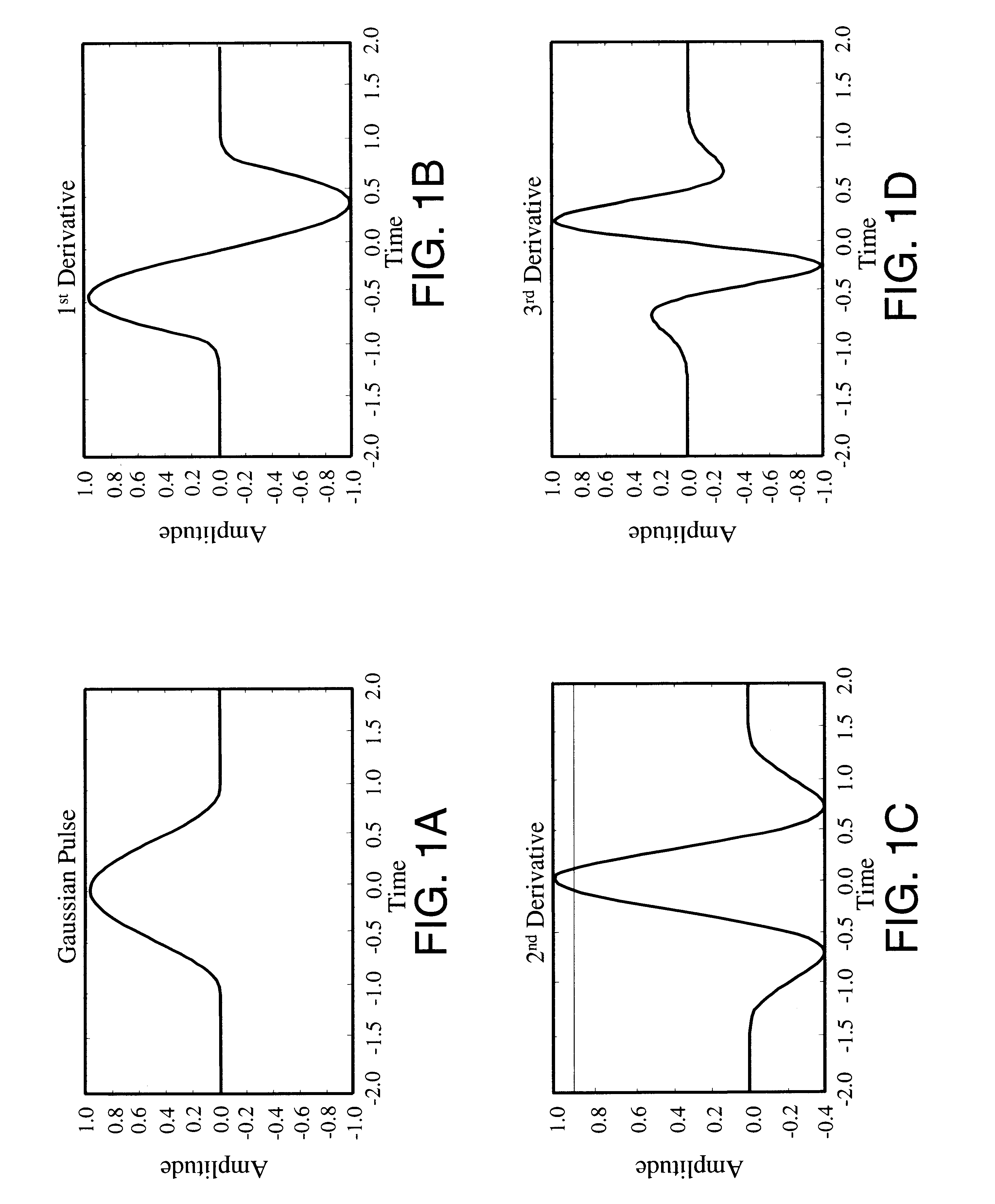
RELATED ARTRecent advances in communications technology have enabled an emerging, revolutionary ultra-wideband technology (UWB) called impulse radio communications systems (hereinafter called impulse radio).Impulse radio has been described in a series of patents, including the following, which are incorporated herein by reference: U.S. Pat. No. 4,641,317, issued Feb. 3, 1987 to Larry W. Fullerton; U.S. Pat. No. 4,813,057, issued Mar. 14, 1989 to Larry W. Fullerton; U.S. Pat. No. 4,979,186, issued Dec. 18, 1990 to Larry W. Fullerton; and U.S. Pat. No. 5,363,108, issued Nov. 8, 1994 to Larry W. Fullerton. A second generation of impulse radio patents include the following, which are incorporated herein by reference: U.S. Pat. No. 5,677,927, issued Oct. 14, 1997 to Fullerton et al.; U.S. Pat. No. 5,687,169 issued Nov. 11, 1997 to Fullerton et al.; and U.S. Pat. No. 5,832,035, issued Nov. 3, 1998 to Fullerton et al.Basic impulse radio transmitters emit short pulses approaching a Gaussian...

Claims


Application Information

Patent Timeline
Patent Type & Authority Patents(United States)
IPC IPC(8): G01S3/14G01S3/50
CPCG01S3/50
Inventor LANGFORD, DAVID W.NIEBURG, MICHAEL J.SHREVE, GREGORY A.
Owner HUMATICS CORP
Why Eureka
Try Eureka