
Printing with selection of sub-scanning

a sub-scanning and printing technology, applied in the field of performing printing, can solve the problems of ink bleed, image degradation due to paper feed error, and the tendency to generate band-form areas of image deterioration called "bands" to become less readily apparent,

Inactive Publication Date: 2004-08-03
KONAMI DIGITAL ENTERTAINMENT CO LTD +1
View PDF8 Cites 51 Cited by
  • Summary
  • Abstract
  • Description
  • Claims
  • Application Information

AI Technical Summary

Benefits of technology

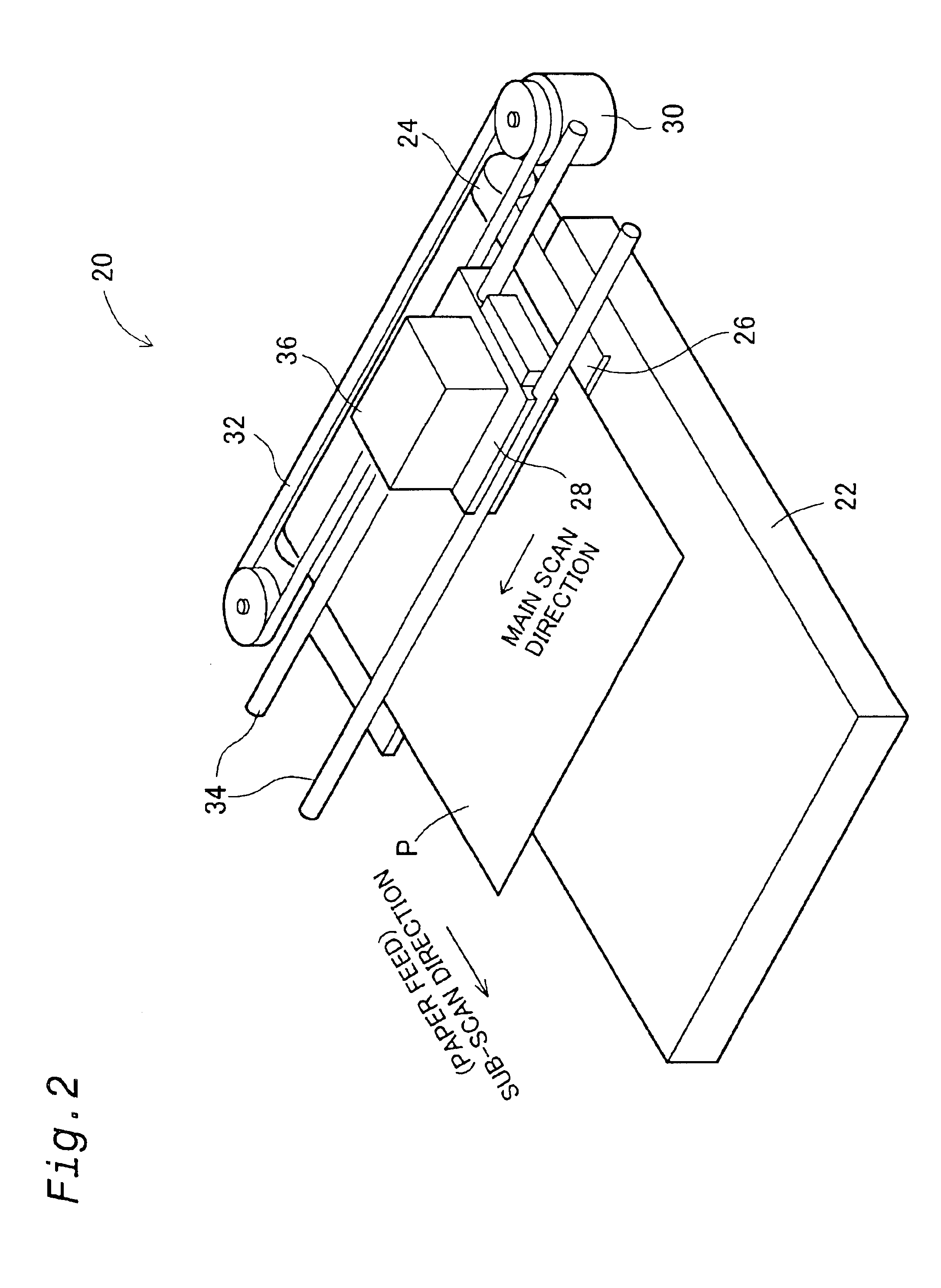
The main cause of paper feed error in this printer 20 is manufacturing error of the paper feed roller 24 (FIG. 4). This manufacturing error includes error in the external diameter and error in the surface roughness. For example, if the external diameter of the paper feed roller 24 is greater than its design value, the feed error is a plus error; if this diameter is smaller than the design value, the feed error is a minus error. In the present embodiment, correction of the paper feed error caused by such manufacturing error in the paper feed roller 24 is corrected for each printer prior to shipping. Accordingly, even if the permissible error of the paper feed roller 24 is set at a somewhat large value, the paper feed error at the time of actual printing can be reduced almost to zero. Furthermore, as the tolerance regarding manufacturing error of the paper feed roller 24 is relaxed, the yield of the paper feed roller 24 is increased, so that the advantage of a reduction in the cost of the printer 20 is also obtained.
In Step S64, the user selects from among the color patches printed in the different dot recording modes that color patch that appears to have the most uniform gray. In Step S66, the user then inputs to the computer the number appended to the selected color patch, by means of the user interface screen of the computer. The computer sends this number to the printer. When the printer receives a print command later, it performs image processing and printing in accordance with the dot recording mode corresponding to the number input in Step S66. By carrying out actual printing in each dot recording mode and then selecting dot recording mode, high quality printing is possible.

Problems solved by technology

In the test pattern that is printed by such a printing method, band-form areas of image deterioration called "banding" tend to be generated as a result of sub-scan feed error.
Typically, if ink duty is excessively large, the ink tends to bleed, whereas conversely if it is too low, there is a tendency for image degradation due to paper feed error to become less readily apparent.
However, depending on the printing system, all of the nozzles are not always used; in some cases, only some of the nozzles are used.
The main cause of paper feed error in this printer 20 is manufacturing error of the paper feed roller 24 (FIG. 4).
This manufacturing error includes error in the external diameter and error in the surface roughness.
When a test pattern is printed utilizing a quasi-band feed such as that shown in FIGS. 11 and 12(A), banding tends to occur at the boundaries of the respective color bands as a result of paper feed error.
However, in cases where the respective patches are printed using the same paper feed amounts and using raster data that simulates the sub-scan feed error as shown in FIG. 19(A), the units of the paper feed amount correction values are limited to integral multiples of the raster line pitch.
That is, if dot recording rate is set to an excessively high value (100%, for example), there is tendency for the ink to bleed, possibly making it difficult to observe black streaks and white streaks.
If, on the other hand, dot recording rate is set to an excessively low value (60%, for example), ink dots will tend to become excessively sparse, possibly making it difficult to observe black streaks and white streaks.

Method used


Image

  • Printing with selection of sub-scanning
  • Printing with selection of sub-scanning
  • Printing with selection of sub-scanning

Examples


second embodiment

C. Modification of the Second Embodiment

The present invention in not limited to the embodiments or examples described above, and various other variations may be implemented within the scope thereof. For example, the variations described below are possible.

modification 1

C1. Modification 1

In the preceding examples, the printing that is performed in the interlace recording mode using the printing head having the nozzle pitch of 2 dots or more. But, this invention is applicable to the printing that is performed using the high density nozzle (that is the printing head whose nozzle pitch k is 1 dot)

modification 2

C2. Modification 2

In the preceding examples, the color patches of the test pattern are gray patches reproduced with black ink only, but it would be possible to use different color patches. For example, single-color test patches reproduced with cyan ink or magenta ink could be used.


PUM


Abstract

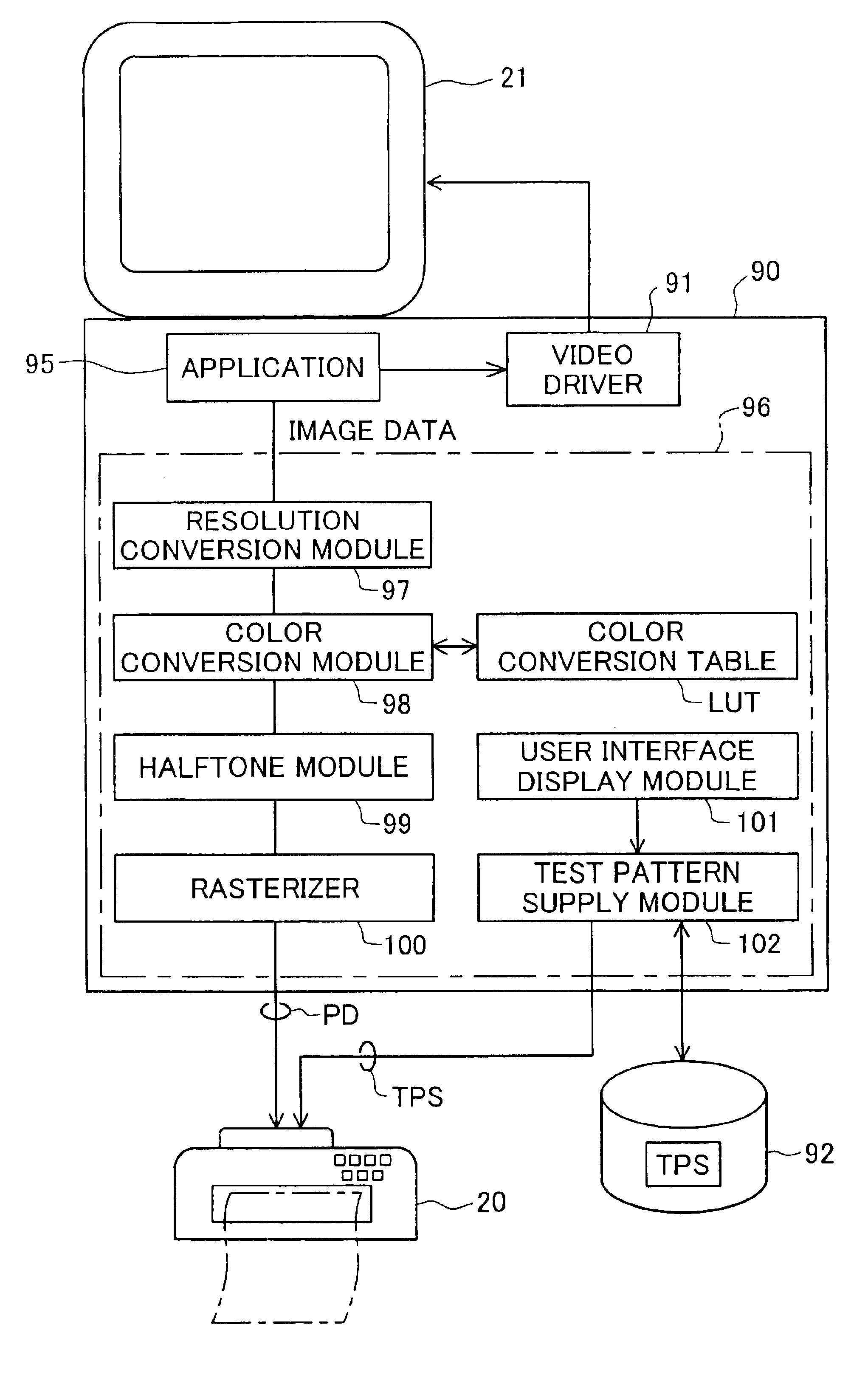
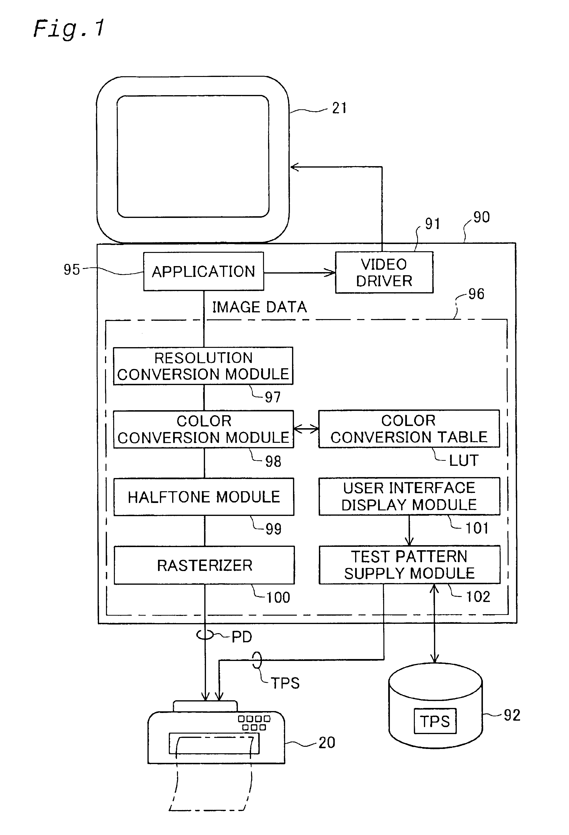
An object of the present invention is to provide a technique that makes it possible to improve the image quality by selecting adequate paper feedings in a printer that performs printing. First, a test pattern is printed according to the interlace recording mode. The test pattern includes a plurality of color patches respectively printed using different correction values. The correction values for respective feed amounts are determined by investigating the printing results of this test pattern. Then, when an image is printed in this interlace recording mode, the sub-scan feed amount is corrected according to this correction value.

Description

1. Field of the InventionThe present invention relates to a technique for performing printing by recording ink dots on a recording medium while a print head is moving in the main scan direction.2. Description of the Related ArtInk jet printers which eject ink from a head and laser printers have become popular as output devices for computers. Especially in recent years, color printers using color inks have also been widely utilized.Various types of printing media for ink jet printers have been commercially marketed. Since the coloring properties of inks differ in different printing media, there are considerable differences in the images obtained. The type of printing medium used also affects the precision of the sub-scan feed of the printing medium (hereafter referred to as the "paper feed"). For example, the actual feed amount may vary considerably between printing media with easy-slip surfaces and printing media with surfaces that do not slip easily, even if the same feed operation...

Claims


Application Information

Patent Timeline
IPC IPC(8): B41J2/15B41J2/145B41J2/21B41J29/393G06K15/10G06K15/02G06K15/16H04N1/00H04N1/047
CPCB41J2/15B41J2/2132B41J29/393G06K15/105G06K15/16H04N1/00002H04N1/00015H04N1/00023H04N1/00031H04N1/00045H04N1/00053H04N1/00063H04N1/00076H04N1/00087H04N1/0473G06K2215/0094H04N2201/0098H04N2201/04756B41J2/145
Inventor YAMASAKI, KEIGOOTSUKI, KOICHI
Owner KONAMI DIGITAL ENTERTAINMENT CO LTD
Learn More