Low-pressure CVD apparatus and method of manufacturing a thin film

a cvd apparatus and low-pressure technology, applied in chemical vapor deposition coatings, coatings, metal material coating processes, etc., can solve the problems of increasing the size of the cvd apparatus, increasing the equipment cost, and relatively high cost of manufacturing a thin film

Inactive Publication Date: 2004-08-03
TANAKA PRECIOUS METAL IND
View PDF24 Cites 40 Cited by
  • Summary
  • Abstract
  • Description
  • Claims
  • Application Information

AI Technical Summary

Benefits of technology

The inventors of the present invention, as a result of investigation for solving the above-described problems, have thought that in order to efficiently recover the used raw material, it is important to increase a cooling efficiency when cooling a used raw material in the trap. Further, as a method for putting such an idea into practical use, the inventors think it is appropriate to fill the gas flowing passage of the trap with an amount of solid fillers. In a commonly used conventional trap, the internal surfaces thereof can serve as effective cooling surfaces. However, since in such a conventional trap there is only a small contact area allowing a contact between a used material and the cooling surfaces, a sufficient cooling of the used raw material is almost impossible. In contrast to this, using an amount of fillers to fill the gas flowing passage of the trap can increase the contact area allowing the desired contact between a used material and the cooling surfaces, thereby ensuring an increased cooling efficiency in the trap.
However, in the LPCVD apparatus of the present invention, besides the trap pressure regulating valve and the by-pass pipe, there is also provided a back-flow valve on the upstream side of the trap in order to prevent a back flow of a fluid from the trap. In addition, it is preferable to provide the by-pass shut-off valves for shutting off an undesired by-pass flow so as to prevent a used raw material gas (flowing from the reactor during the thin film manufacturing process) from directly flowing into the exhaust pump.

Problems solved by technology

However, the inventors of the present invention have recently developed a recycle technique in order to solve an existing problem, i.e., the cost for manufacturing a thin film is relatively high because of a low efficiency in using the raw material compound in the CVD method.
However, an increase in the capacity of a trap will undesirably cause an increase in the size of a CVD apparatus, thus causing an increase in the equipment cost.
Moreover, an increase in the capacity of a trap can also reduce an exhaust efficiency of an exhaust pump, thus undesirably reducing the functions originally provided by the trap.
However, since in such a conventional trap there is only a small contact area allowing a contact between a used material and the cooling surfaces, a sufficient cooling of the used raw material is almost impossible.
However, if an amount of fillers are loaded into the trap with a high density, a pressure loss across the trap will be large, and this will make it difficult for an exhaust pump to carry out an exhaust operation.
As a result, a pressure dropping speed in the reactor will be reduced, bringing about an undesired influence to the reaction in which a thin film is formed.
For this reason, the commonly used pellet-like fillers are considered to be not appropriate for being loaded into the trap.
Further, as to the size of the fillers, it is preferable that the length thereof is in a range of 0.01 to 1.0 m. If the length is shorter than 0.01 m, it will be difficult to effect a sufficient cooling of the used raw material.
On the other hand, if the length is longer than 1.0 m, not only an undesired influence will be brought about to the cooling efficiency, but also the trap has to be made large in its size and this will cause a decrease in the exhaust efficiency.
If the hole diameter is smaller than 0.5 mm, a pressure loss caused due to the fillers will be large, and the holes will get choked by the used and condensed raw material.
On the other hand, if the hole diameter is larger than 10 mm, it will be difficult to cool the used raw material to a sufficient extent.
Since most of the metallic compounds (organic compounds) used in the CVD method have a relatively low vapor pressure, they are not easy to be condensed under a low pressure and at a low temperature.

Method used


Image

  • Low-pressure CVD apparatus and method of manufacturing a thin film
  • Low-pressure CVD apparatus and method of manufacturing a thin film
  • Low-pressure CVD apparatus and method of manufacturing a thin film

Examples


first embodiment

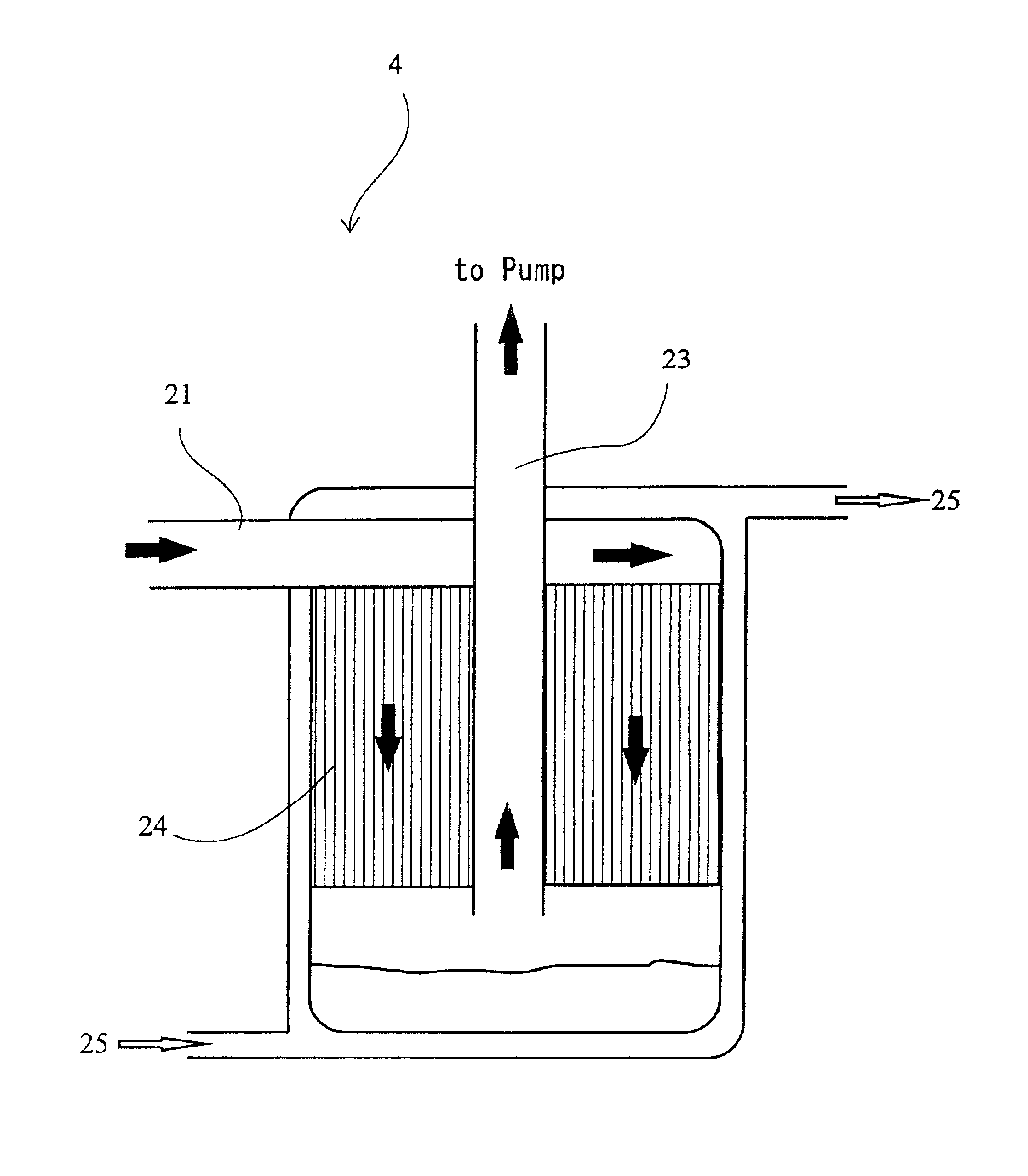
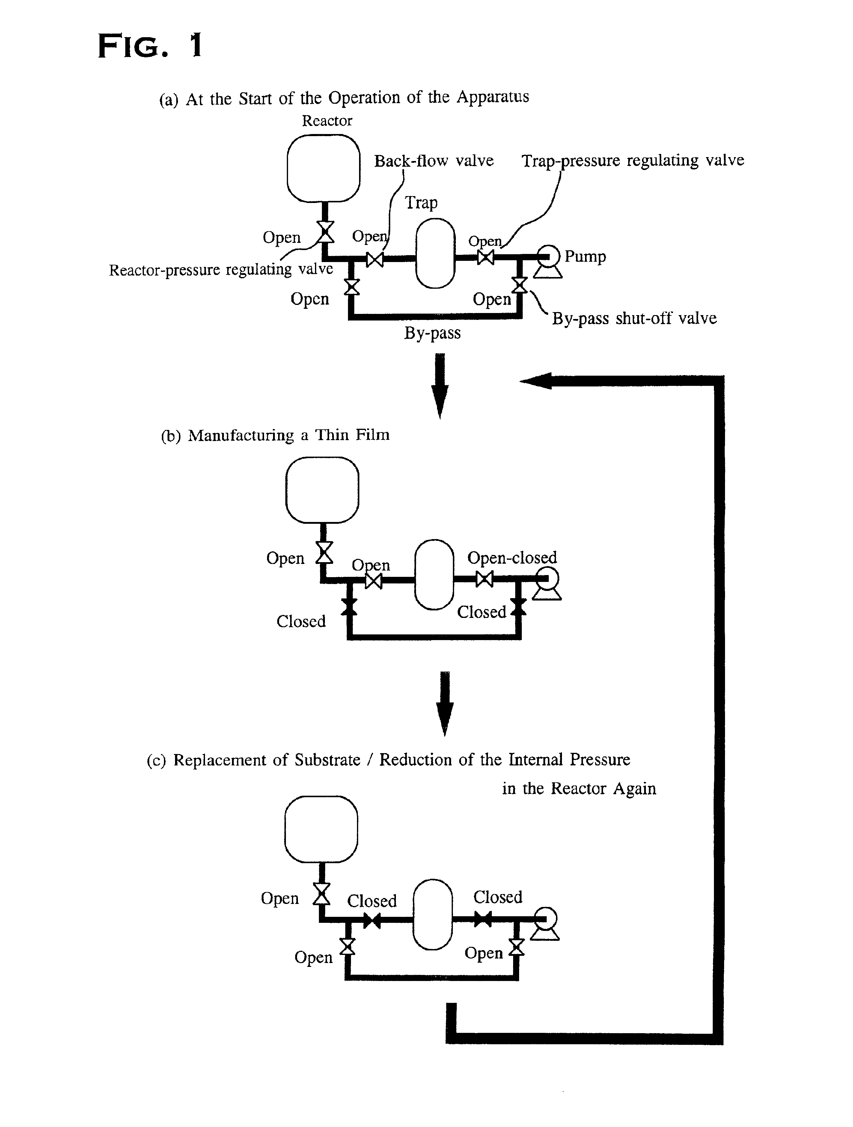
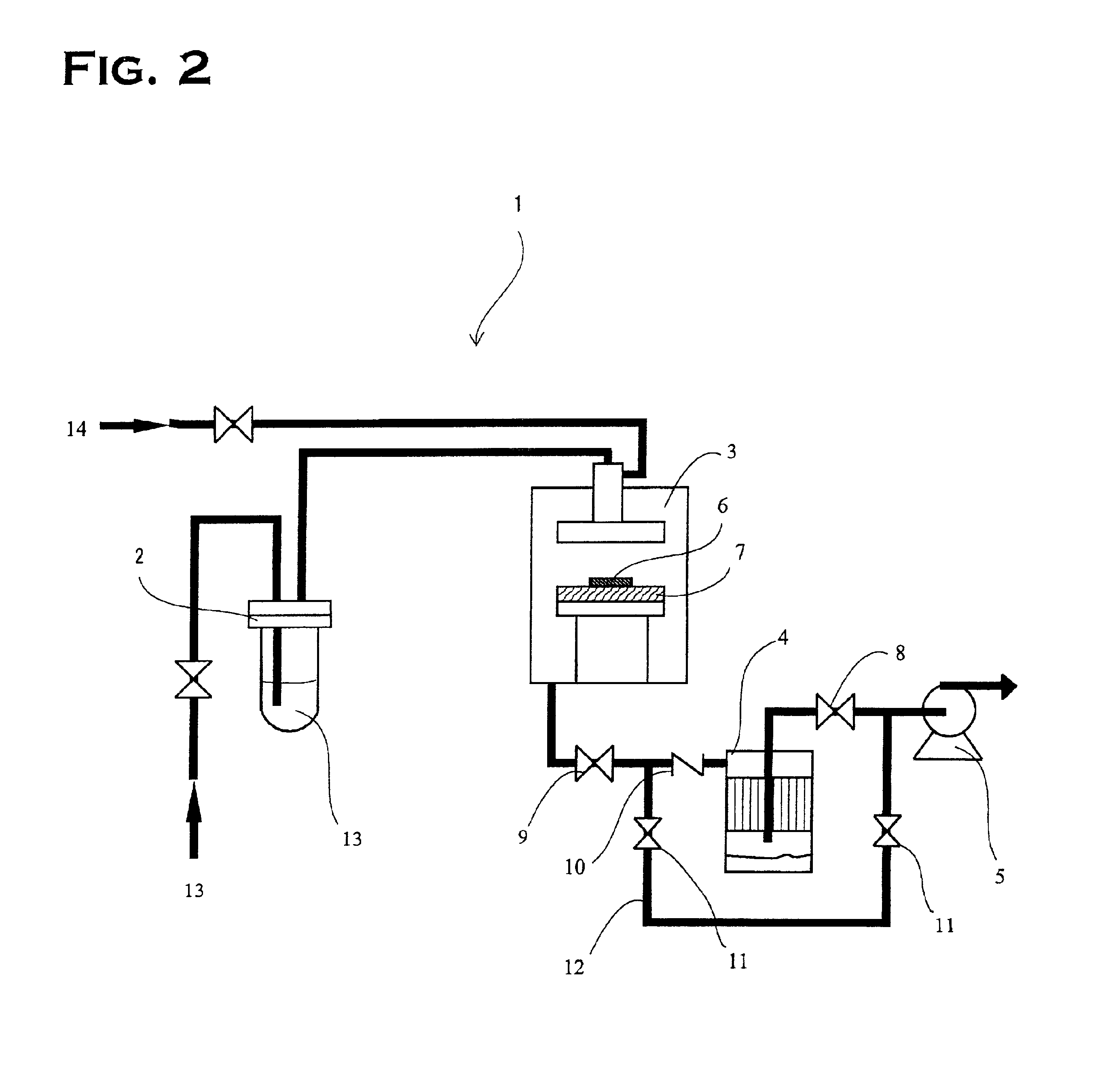
FIG. 2 is a schematic view showing an LPCVD apparatus used in the present embodiment. The LPCVD apparatus 1 shown in FIG. 2 comprises a thermostat 2 serving as a container for enclosing an amount of organometallic compound, a reactor 3, a trap 4 for cooling and condensing a raw material gas used in the reaction, and an exhaust pump 5 for reducing an internal pressure in the reactor 3 and an internal pressure in the trap 4. The reactor 3 contains a substrate 6 and a heater 7 for heating the substrate 6. Further, in the present embodiment, a trap pressure regulating valve 8 for regulating an internal pressure in the trap 4 is disposed between the trap 4 and the exhaust pump 5. Moreover, a reactor pressure regulating valve 9 for regulating an internal pressure in the reactor 3 is provided on the downstream side of the reactor 3. A back-flow valve 10 is provided on the upstream side of the trap 4. In addition, between the downstream side of the reactor pressure regulating valve 9 and th...


PUM

PropertyMeasurementUnit
lengthaaaaaaaaaa
lengthaaaaaaaaaa
lengthaaaaaaaaaa

Abstract

An LPCVD apparatus comprising: a container for accommodating an organometallic compound which serves as a raw material; a heating means for heating the container and vaporizing the organometallic compound to obtain a raw material gas; a reactor for accommodating a substrate on which a thin film being precipitated; an exhaust pump for maintaining a low pressure atmosphere within the reactor; and a trap provided on the upstream side of the exhaust pump and cooling used raw material gas supplied from the reactor. In the reactor, the trap is provided with honeycomb-structure cylindrical fillers in a flowing passage through which the used raw material flows. The LPCVD apparatus according to the present invention enables recovery of a larger amount of used raw material without reducing its exhaust efficiency.

Description

1. Technical Field of the InventionThe present invention relates to an apparatus for carrying out a process for forming a metal film or a metallic compound film with the use of LPCVD method, also relates to a method for controlling the film formation process.2. Description of the Related ArtSince chemical vapor deposition method (hereinafter referred to as CVD method) can be used to produce a uniform film, and since CVD method has an excellent capability called "step coverage" which can be effectively used to form a uniform film on an uneven surface, this method has become one of generally used thin film formation techniques for forming thin film electrodes in a semiconductor device.A thin film formation process involved in the CVD method requires that after a raw material has been vaporized and moved to the surface of a substrate, the particles of the raw material are caused to react with one another on the substrate so as to be accumulated thereon. Particularly, in recent years, t...

Claims


Application Information

Patent Timeline
Patent Type & Authority Patents(United States)
IPC IPC(8): C23C16/44C23C16/18
CPCC23C16/18C23C16/4412
Inventor SAITO, MASAYUKI
Owner TANAKA PRECIOUS METAL IND
Why Eureka
Try Eureka