PCI riser card bracket assembly

a technology of riser card and bracket assembly, which is applied in the direction of electrical apparatus casing/cabinet/drawer, coupling device connection, instruments, etc., can solve the problems of not being able to physically fit the card within the housing, the inability to add to or enhance the functionality of the computer system, and the size constraints of the computer system housing

Inactive Publication Date: 2004-08-03
ORACLE INT CORP
View PDF9 Cites 47 Cited by
  • Summary
  • Abstract
  • Description
  • Claims
  • Application Information

AI Technical Summary

Problems solved by technology

One limitation on the ability to add to or enhance the functionality of the computer system is the size constraints of the computer system housing.
In particular, the height constraints placed on the system can dictate whether any cards can be directly attached to the motherboard and if so, the physical dimensions of the card.
For example, if the height of the card is greater than the height limitation of the computer system housing, there will not be enough room to physically fit the card within the housing.
While minimizing the effects of the height restriction, locating the cards parallel to the motherboard can create problems for physically connecting the components of the computer system to one another.
Since the cards are not directly connected to the motherboard, additional connectors are required and problems with alignment and support for the cards can become issues.
For example if the cards, additional connectors and motherboard are not physically aligned correctly, a connection between the components may be difficult.
If a connection can be physically accomplished, forces acting on the components, due to any misalignment or movement of the computer system, may result in mechanical failure of one or more of the components, either immediately or at some future time.
Such stress forces imposed on the components can cause traces to crack and fail, solder joints to become loosened, and board-level devices to fail.

Method used


Image

  • PCI riser card bracket assembly
  • PCI riser card bracket assembly
  • PCI riser card bracket assembly

Examples


Embodiment Construction

Illustrative embodiments of the invention are described below. In the interest of clarity, not all features of an actual implementation are described in this specification. It will of course be appreciated that in the development of any such actual embodiment, numerous implementation-specific decisions must be made to achieve the developers' specific goals, such as compliance with system-related and business-related constraints, which will vary from one implementation to another. Moreover, it will be appreciated that such a development effort might be complex and time-consuming, but would nevertheless be a routine undertaking for those of ordinary skill in the art having the benefit of this disclosure.

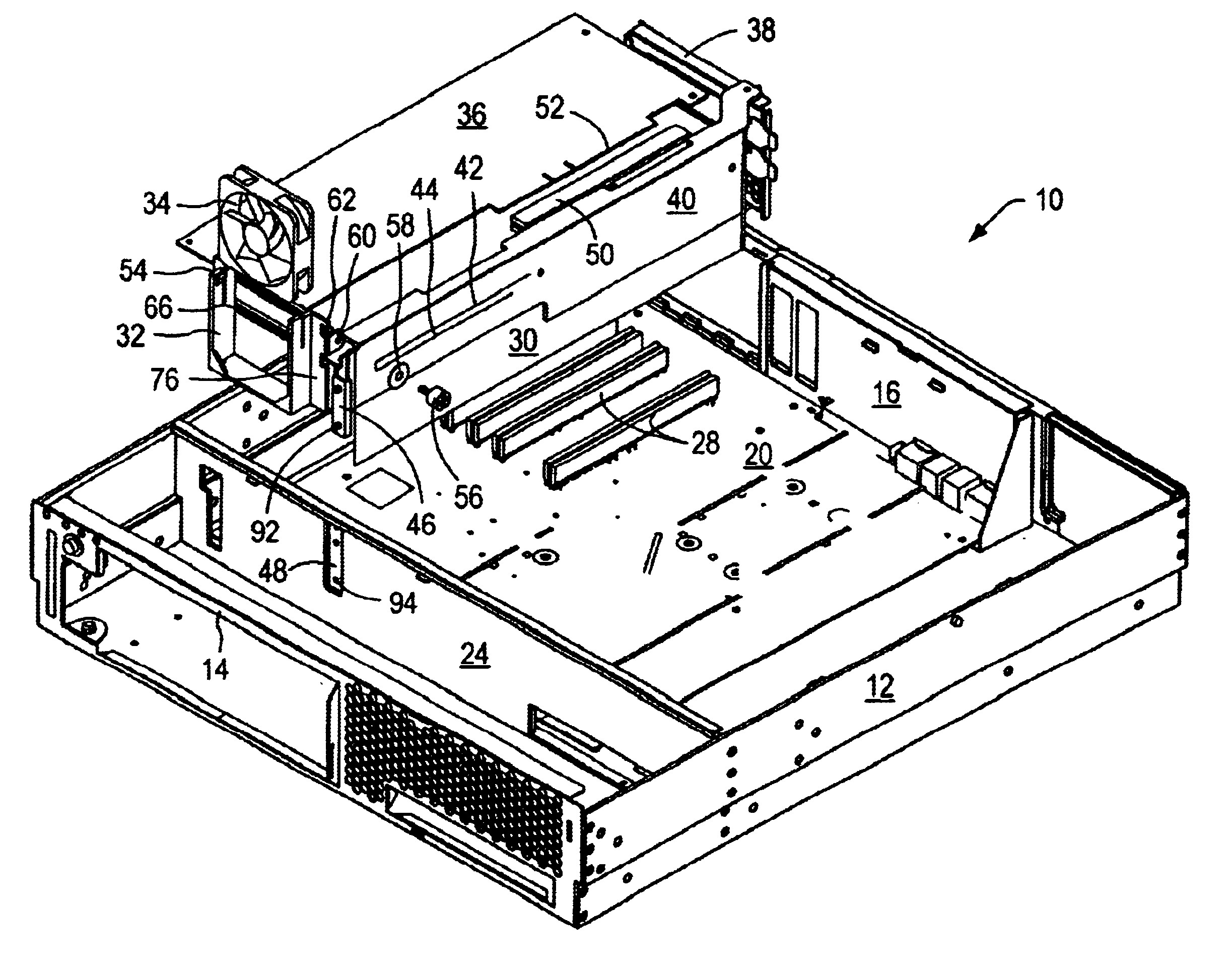
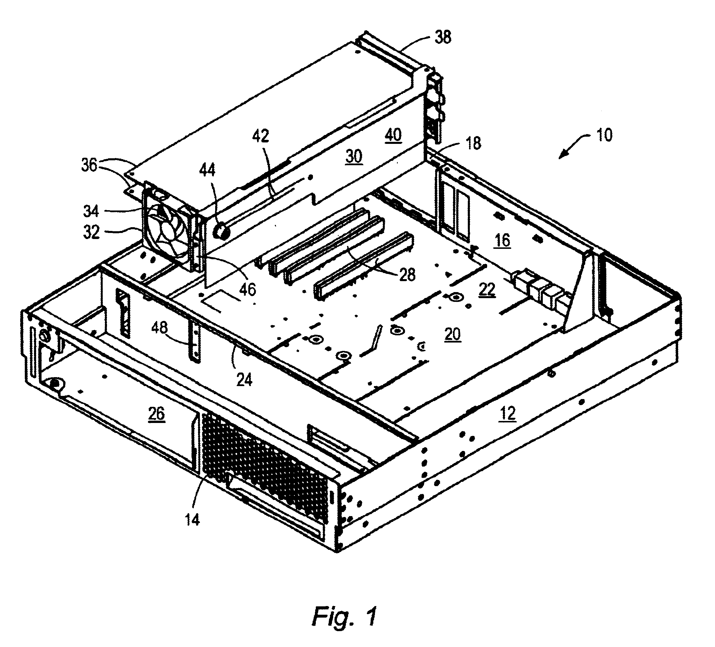
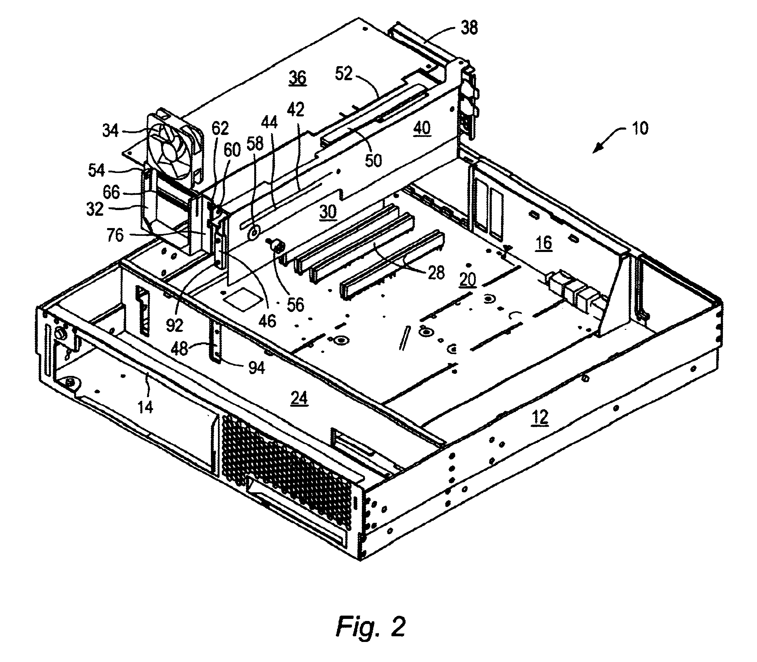
Referring to the attached drawings, FIG. 1 is a partially exploded perspective view of a computer assembly 10 comprising a chassis 12 with a front enclosure 14 and a rear enclosure 16. Within this application the term "computer assembly" can be used to refer to electronic assemblies, e...


PUM


Abstract

The present invention discloses methods and apparatus for installing printed circuit boards within an electronic assembly. One embodiment is a riser card bracket assembly for an electronic system. The riser card bracket comprises an adjustable card retainer disposed within the riser card bracket assembly; the retainer is capable of movement within the riser card bracket assembly to secure cards of various lengths. Another embodiment of the invention is a method for installing cards within a computer housing having a motherboard. The method comprises providing a riser card bracket assembly having an adjustable card retainer. At least one card is inserted within the riser card bracket assembly. The riser card bracket assembly is inserted within the computer housing whereby the at least one card is positioned parallel to the motherboard. A portion of the riser card bracket assembly is inserted into a connector located on the motherboard, thereby creating electrical connection between the card and the motherboard.

Description

1. Field of the InventionThis invention relates generally to the placement of components within an electrical assembly, and, more particularly, to the placement and support of peripheral component interface (PCI) bus cards within a computer system.2. Description of Related ArtComputer systems are general-purpose devices that may be modified to perform particular tasks or functions. Generally, computer systems include a motherboard, a power source and other components mounted within a cabinet. The motherboard typically includes a number of connectors or slots in which special purpose printed circuit boards, often referred to as peripheral component interface (PCI) bus cards or "cards", may be inserted. These special purpose cards may be used to add to or enhance the functionality of the computer system. For example, a conventional computer system may have its graphics capability enhanced by the addition of a graphics card. Similarly, the sound-producing capability of the computer sys...

Claims


Application Information

Patent Timeline
Patent Type & Authority Patents(United States)
IPC IPC(8): G06F1/18H05K7/14
CPCG06F1/184G06F1/185G06F1/186H05K7/1408
Inventor KIM, DAVID K. J.RUCKMAN, WILLIAM W.
Owner ORACLE INT CORP
Why Eureka
Try Eureka