
Method of printing variable information

a variable information and printing technology, applied in the field of printing variable information, can solve the problems of large technology complexity of xerographic printing, limited process speed, needing to use toner, etc., and relatively expensive production cos

Inactive Publication Date: 2004-08-24
KODAK IL
View PDF11 Cites 16 Cited by
  • Summary
  • Abstract
  • Description
  • Claims
  • Application Information

AI Technical Summary

Problems solved by technology

Although xerographic printing has a great complexity of technology, it has the ability to vary information from print to print, whereas offset has a fixed master.
Two of the big disadvantages of electro-photography are the need to use a toner and the limits of the speed of the process due to its complexity.
The toner, which is particulate in structure, is relatively expensive to produce and has a limit to the minimum size of particles, which also affects quality of reproduction.
Also, current flows from electrode tips and it is difficult to direct it in an accurate manner, because it can flow from any point on the surface of the electrode, resulting in poor image quality.
However, the ink jet process has difficulty printing good quality color work on a variety of printing stock.

Method used


Image

  • Method of printing variable information
  • Method of printing variable information

Examples


examples

The following descriptions are by way of example to illustrate the method as described.

example i

The following ink was formulated (The formulation is by percentage parts in weight):

A piece of uncoated aluminum was first cleaned with sodium silicate and then with methyl ethyl ketone. It was coated with a 4 micron thick layer of the above ink, using a wire wound rod. A flash exposure was made using UV light with an energy density of 150 microjoules per square centimeter. The coating was squeegeed with a rubber blade, removing non-imaged material. The coated aluminum was dipped, coating side down, into distilled water and then placed image side down on a piece of paper. A metal roller was rolled over the backside of the aluminum and the aluminum removed, leaving on the paper a sharp red image with no background. There was no material remaining on the aluminum. The image was cured by exposing to UV.

example ii

The following composition (Mixture 1) was mixed and ball milled for 24 hours (all parts by weight):

Before coating onto 175 micron polyester, 3.9 grams of Cycat 4040 (Dyno-Cytec, Botleweg 175, 3197 KA Rotterdam, Netherlands) were added. The mixture was coated with a wire wound rod to a dry weight of 10 grams per square meter and then cured in the oven for 5 minutes at 140.degree. C.

This material provided an example of surface 11. The surface was then treated, by rubbing silicone oil into it, using a soft piece of material. The following mixture was then made up:

This mixture was coated with a rod to a weight of 4 grams per square meter, onto the surface prepared and described above. It was then exposed using a Lotem infrared plate setter using an exposure equivalent to approximately 5 millijoules per square centimeter. This energy was sufficient to gel the mixture by heat transference from the black layer described above. The non-imaged material was squeegeed off with a rubber blade a...


PUM

PropertyMeasurementUnit
thicknessaaaaaaaaaa
thicknessaaaaaaaaaa
energyaaaaaaaaaa

Abstract

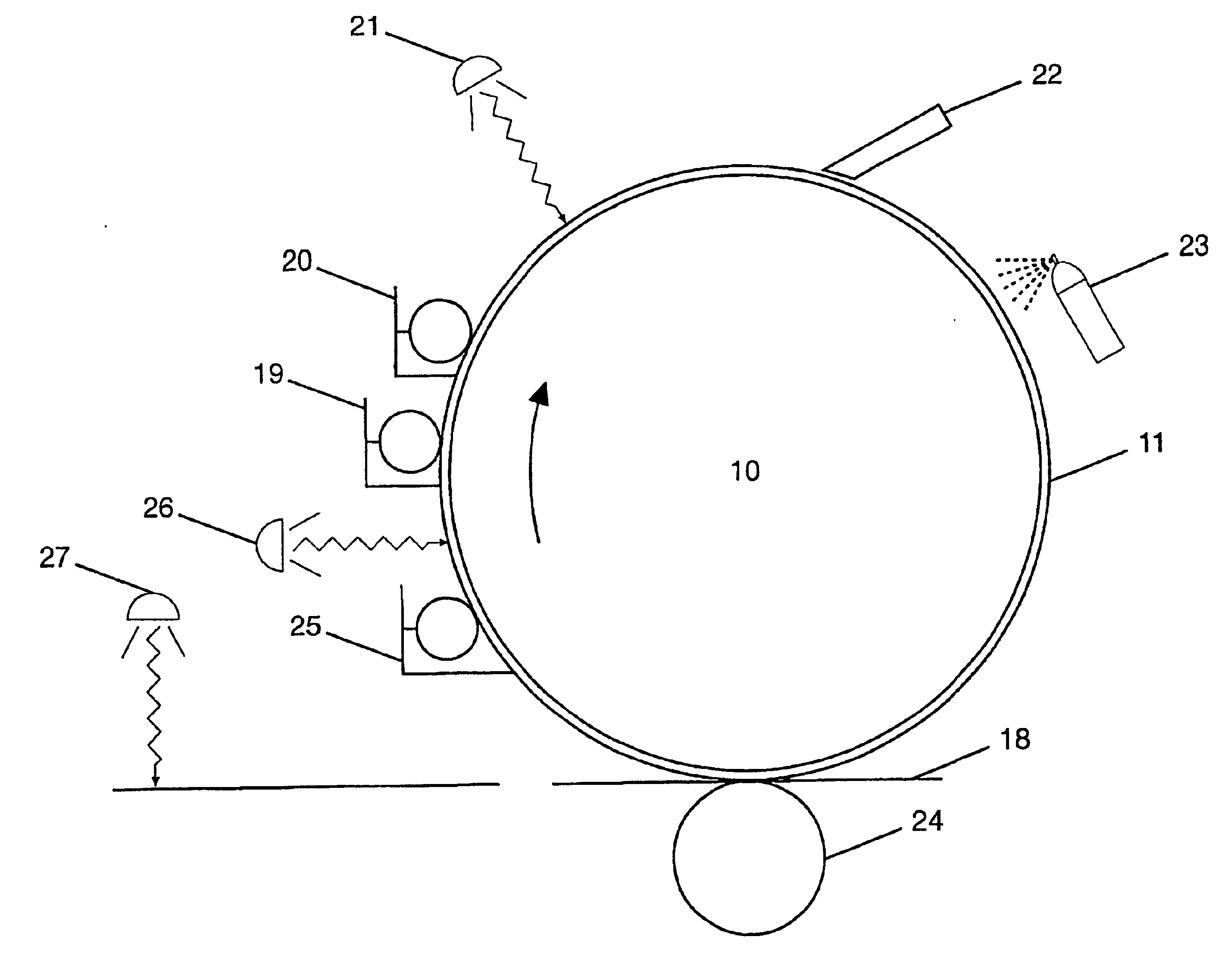
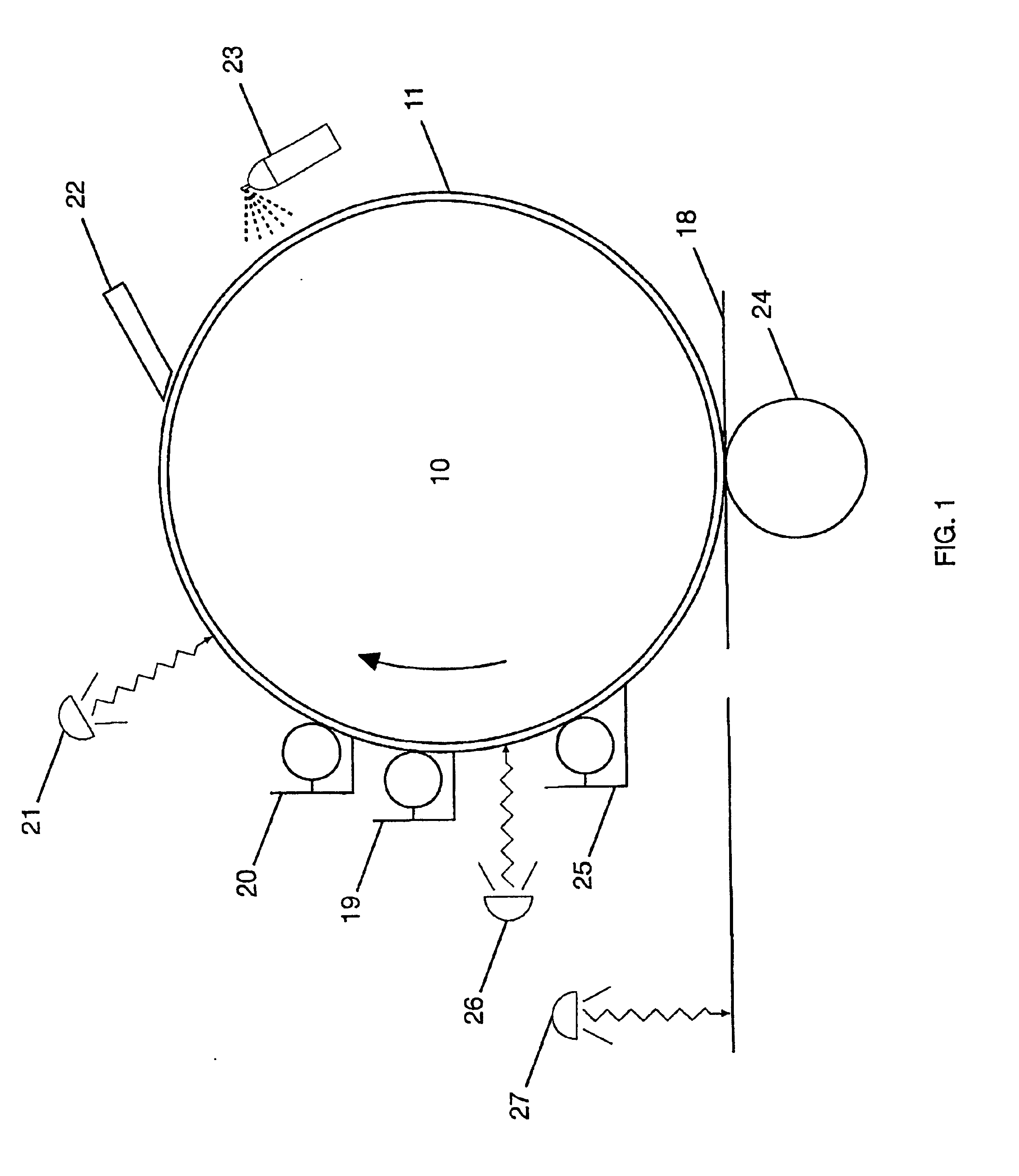
The gel method of printing variable information of the present invention involves applying inks onto a substrate that is part of or attached to a cylinder of the printing machine. Imaging is by means of an energy source in the UV, visible or infrared regions, modulated to represent a digital image pattern that has been composed on a computer. The consequence of imaging is to gel the ink and increase its adhesion to the substrate of the printing cylinder. The non-gelled background ink with lower adhesion is then removed by a squeegee action and returned to an ink reservoir. The remaining image is transferred to an offset blanket or directly to print stock by pressure. The process does not use a master, but produces an image that is erased after printing with each cylinder rotation so that the next rotation producing the next print can have fresh information written upon it.

Description

The present invention relates to a gel method of printing variable information, more particularly to a printing method involving a special ink, which is gelled by means of an energy source.BACKGROUND TO THE INVENTIONIn recent years, copying and printing technologies have begun to merge. Copying may be described as the ability to reproduce an original document one or more times. Printing may be described as creating a master that can be used to produce multiple impressions. Both processes create multiple copies of identical information.For many years, copying has been dominated by electro-photography and more specifically xerography. An important means of printing that has been strongest in the market for printing impressions onto paper is offset lithography. Development and wide distribution of computers has enabled origination for printing to be prepared in an electronic form. While the need to copy documents is still widespread, documents can also be generated directly from comput...

Claims


Application Information

Patent Timeline
Patent Type & Authority Patents(United States)
IPC IPC(8): B41C1/10B41M1/06B41M5/025B41M5/06B41M1/00
CPCB41C1/105B41M1/06B41M5/06Y10S101/29
Inventor FIGOV, MURRAYSIGALOV, ANNA
Owner KODAK IL
Learn More