Compact wide scan periodically loaded edge slot waveguide array

a waveguide array and wide scan technology, applied in the direction of linear waveguide fed arrays, direction finders using radio waves, instruments, etc., can solve the problems of increasing the array weight, increasing the insertion loss, and consuming a large amount of serpentine spa

Inactive Publication Date: 2004-08-24
RAYTHEON CO
View PDF11 Cites 16 Cited by
  • Summary
  • Abstract
  • Description
  • Claims
  • Application Information

AI Technical Summary

Problems solved by technology

However, the serpentine type of waveguide array uses considerable space for the serpentine.
Another approach is to use dielectric loading in the waveguide, which not only increases the array weight but also increases the insertion loss significantly.

Method used


Image

  • Compact wide scan periodically loaded edge slot waveguide array
  • Compact wide scan periodically loaded edge slot waveguide array
  • Compact wide scan periodically loaded edge slot waveguide array

Examples


Embodiment Construction

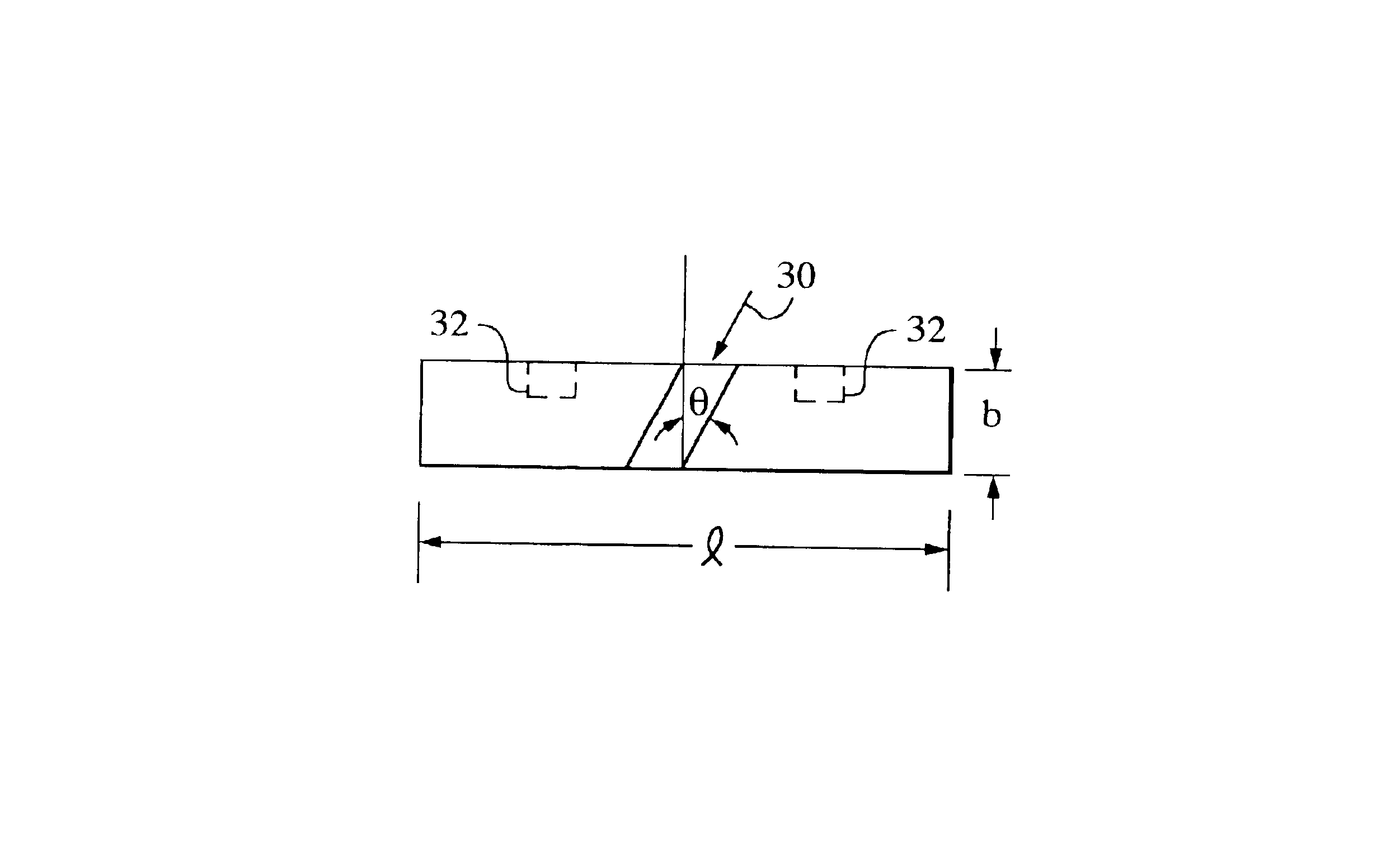
In order to achieve a larger scan range in the elevation plane and to obtain an extended frequency scan in the azimuth plane for a monopulse antenna, a periodically loaded edge slot array is needed. For an exemplary application for this invention, an edge slot array with half-height waveguide is desirable. A periodically loaded edge slot design with half-height waveguide using a different loading approach in accordance with aspects of this invention can meet this need.

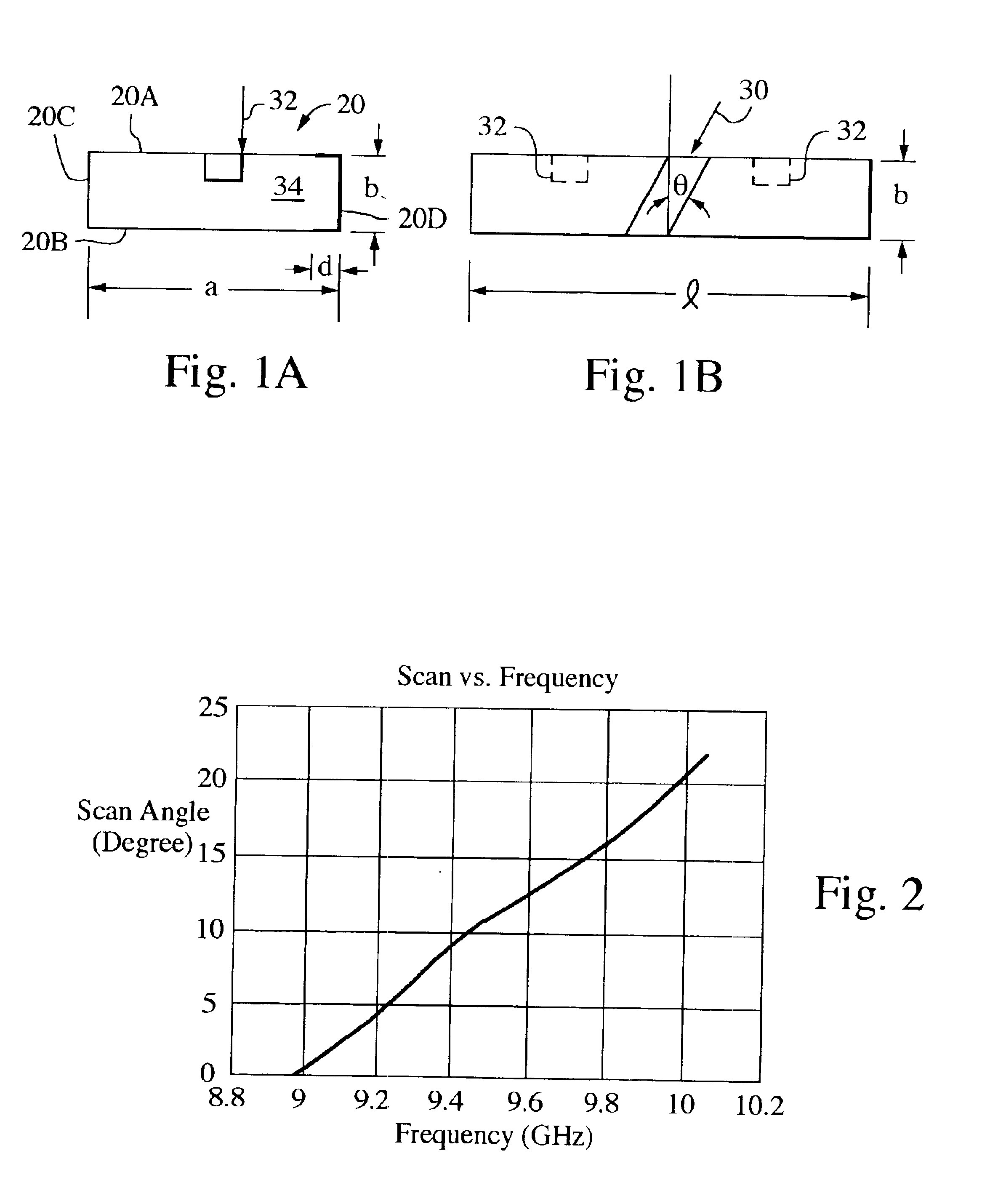
FIGS. 1A and 1B illustrate an exemplary embodiment of a unit element of a periodically loaded edge slot array in accordance with aspects of the invention. The effective electrical length of the unit element is selected based on the desirable scan range and frequency band of interest. It is also typically selected so that the grating lobes do not show up in the region of interest. For example, an electrical length between half wavelength and full wavelength in the periodically loaded waveguide (at the center frequency) ...


PUM


Abstract

A unit element of a periodically loaded edge slot array includes a reduced-height waveguide section having top and bottom walls and opposed first and second sidewalls defining a waveguide space. A slot is formed in the first side wall at an angle with respect to a waveguide longitudinal axis. At least one conductive post protrudes from the top wall into the waveguide space. The unit element can be incorporated into sticks of an electronically scanned antenna.

Description

BACKGROUND OF THE DISCLOSUREThe conventional approach to increase the scan angle of an edge slot array is to use a serpentine type waveguide array. However, the serpentine type of waveguide array uses considerable space for the serpentine. Another approach is to use dielectric loading in the waveguide, which not only increases the array weight but also increases the insertion loss significantly. A longitudinal slot in the broad wall has been used but the broad wall design restricts the scan range (in the plane orthogonal to the waveguide axis).SUMMARY OF THE DISCLOSUREA unit element of a periodically loaded edge slot array includes a reduced-height waveguide section having top and bottom walls and opposed first and second sidewalls defining a waveguide space. A slot is formed in the first side wall at an angle with respect to a waveguide longitudinal axis. At least one conductive post protrudes from the top wall into the waveguide space. The unit element can be incorporated into sti...

Claims


Application Information

Patent Timeline
Patent Type & Authority Patents(United States)
IPC IPC(8): H01Q13/22H01Q13/20H01Q21/00H01Q21/06
CPCH01Q13/22H01Q21/005H01Q21/068
Inventor LEE, KUAN M.KRUEGER, REINHARDT W.YANG, FANGCHOU
Owner RAYTHEON CO
Why Eureka
Try Eureka