Slotted waveguide antenna, signal transmission device and signal continuous transmission system

A waveguide antenna and signal transmission technology, applied to leaky waveguide antennas, circuits, etc., can solve problems such as equipment consumption, and achieve the effect of saving space, saving equipment costs, and small size

Active Publication Date: 2016-01-27
中电科微波通信(上海)股份有限公司
View PDF8 Cites 10 Cited by
  • Summary
  • Abstract
  • Description
  • Claims
  • Application Information

AI Technical Summary

Problems solved by technology

However, this not only consumes equipment, but also requires additional laying space, especially in rail transit, the laying space in the tunnel is already quite compact, and it is impossible to find extra laying space to lay the second set of waveguide antennas

Method used


Image

  • Slotted waveguide antenna, signal transmission device and signal continuous transmission system
  • Slotted waveguide antenna, signal transmission device and signal continuous transmission system
  • Slotted waveguide antenna, signal transmission device and signal continuous transmission system

Examples


Embodiment 1

[0048] figure 1 It is a schematic structural diagram of the continuous signal transmission system in Embodiment 1 of the present invention.

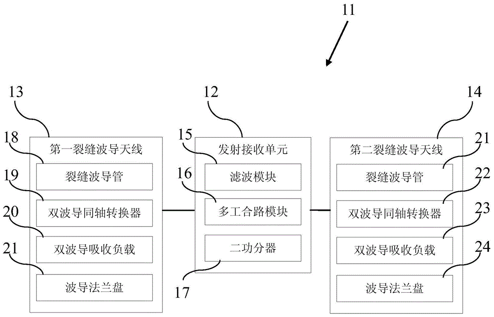
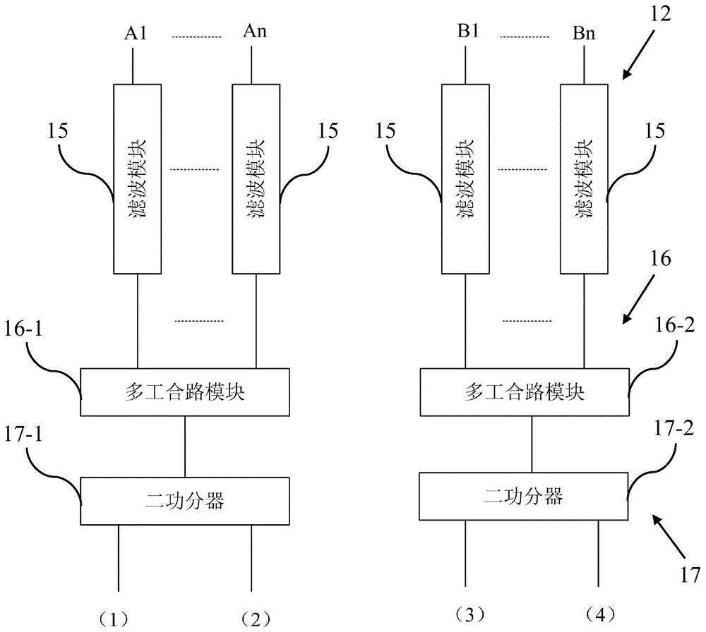
[0049] Such as figure 1 As shown, the continuous signal transmission system 10 is used to continuously transmit two types of electromagnetic wave signals, A and B, whose frequency intervals cannot meet the predetermined isolation requirements. It includes three signal transmission devices, which serve as the first signal from left to right. The transmission device 11, the second signal transmission device 11 and the third signal transmission device 11'.

[0050] The three signal transmission devices are spaced apart from each other at predetermined intervals and arranged along the direction of continuous transmission of signals in rail transit to transmit two types of electromagnetic wave signals. Such as figure 1 As shown, three signal transmission devices are arranged along the direction from left to right to transmit electromagneti...

Embodiment 2

[0129] The following is the description of the second embodiment.

[0130] In the second embodiment, the same symbols are assigned to the same structures as those in the first embodiment, and the same descriptions are omitted.

[0131] Figure 15 It is a schematic structural diagram of the continuous signal transmission system in Embodiment 2 of the present invention.

[0132] Such as Figure 15 As shown, the continuous signal transmission system 100 has X signal transmission devices 110 . The X number of signal transmission devices 110 are spaced apart from each other at predetermined distances, arranged along the direction of continuous transmission of signals in rail transit, and transmit two types of electromagnetic wave signals. In the second embodiment, the predetermined distance is 400-600 meters.

[0133] Among the X signal transmission devices 110, each signal transmission device 110 has a transmitting and receiving unit 120 and a slotted waveguide antenna.

[01...


PUM


Abstract

The invention provides a slotted waveguide antenna that can be laid in an existing space, effectively isolates signals which cannot reach isolation requirements and separately transmits the signals, and also provides a signal transmission device and a signal continuous transmission system that both comprise the slotted waveguide antenna. The slotted waveguide antenna is characterized by comprising at least one slotted waveguide tube for transmitting electromagnetic wave signals, wherein the slotted waveguide tube at least comprises a first pipeline and a second pipeline parallel to each other, the surface of each of the first pipeline and the second pipeline is equipped with multiple slots that enable the electromagnetic wave signals to be transmitted between the inside of each pipeline and the outside of each pipeline, and the first pipeline and the second pipeline are respectively used for transmitting two types of electromagnetic wave signals, wherein the frequency interval between the two types of electromagnetic wave signals cannot reach preset isolation requirements.

Description

technical field [0001] The invention relates to the field of wireless signal transmission, in particular to a slotted waveguide antenna capable of realizing continuous propagation of electromagnetic wave signals, a signal transmission device containing the slotted waveguide antenna, and a continuous signal transmission system. Background technique [0002] With the development of wireless technology, the application of wireless communication technology is becoming more and more extensive. In wireless communication systems, there are three main transmission methods for electromagnetic wave signals: antenna-based free wave transmission, leaky cable transmission, and cracked waveguide transmission. . [0003] The free wireless transmission method uses a directional antenna as the communication medium between the vehicle and the ground. It has less installation restrictions and is more convenient for installation and construction. However, the signal attenuation is faster, the c...

Claims


Application Information

Patent Timeline
Patent Type & Authority Applications(China)
IPC IPC(8): H01Q13/20
Inventor 杨福慧徐凡陈俊华赵朝娜潘丹
Owner 中电科微波通信(上海)股份有限公司
Why Eureka
Try Eureka