Broadband predistortion linearizer

a linearizer and wideband technology, applied in the direction of amplifiers with coupling networks, amplifiers with semiconductor devices/discharge tubes, amplifier modifications to reduce noise influence, etc., can solve the problems of small delay, relatively complicated devices of sato et al., and difficult implementation

Inactive Publication Date: 2004-09-07
ALCATEL LUCENT SAS
View PDF12 Cites 16 Cited by
  • Summary
  • Abstract
  • Description
  • Claims
  • Application Information

AI Technical Summary

Benefits of technology

The device of the invention makes it possible to perform linearization over a broad band of frequencies. It can be implemented at low cost and using a microwave integrated circuit technique. It can be used in all of the frequency bands presently in use for space telecommunications. Circuit adjustment is easy and reproducible, which gives rise to savings in implementation.
In a preferred embodiment, at least one of said linear path and said non-linear path includes a transmission line of adjustable length so as to make it possible starting from equal group propagation time between the paths to modify said parameter and thus adjust the recombination phase as a function of frequency, and consequently adjust the frequency response of the linearizer in this manner in order to compensate the frequency response of the amplifier to be linearized.

Problems solved by technology

That type of amplifier introduces a small amount of delay (due to the finite propagation speed of electrons in a vacuum) in the amplified signal relative to the non-amplified signal.
The device of Sato et al. is relatively complicated because there are two corrector members upstream and downstream from a power splitter and a power combiner that are connected together by the two paths referred to as the linear path and the non-linear path.
Nevertheless, it suffers from various major drawbacks which make implementation difficult.
a first drawback lies in the fact that the operations of initially adjusting the circuits for correcting the amplitude / frequency characteristic and the corrector of the phase / frequency characteristic are often lengthy and difficult to perform, with the task being made more complicated in the usual case where the electrical lengths of the two paths are generally very different; and
a second drawback of prior art devices is that the width of the optimum operating band of the device for correcting non-linearities is limited by differences or differential variations in the electrical lengths of the two paths, either as a function of the frequency or as a function of the amplitude of the signals to be amplified, or else as a function of operating conditions, and in particular temperature.
Nevertheless, those known devices present complex structures relying on a plurality of microwave integrated circuits.
They are difficult to adjust and they are sensitive to temperature.
In addition, they are generally expensive and bulky, which is a severe drawback for numerous applications, and in particular applications in space.
Their use at high frequencies such as the Ka band around 20 GHz would appear to be difficult.

Method used


Image

  • Broadband predistortion linearizer
  • Broadband predistortion linearizer
  • Broadband predistortion linearizer

Examples


Embodiment Construction

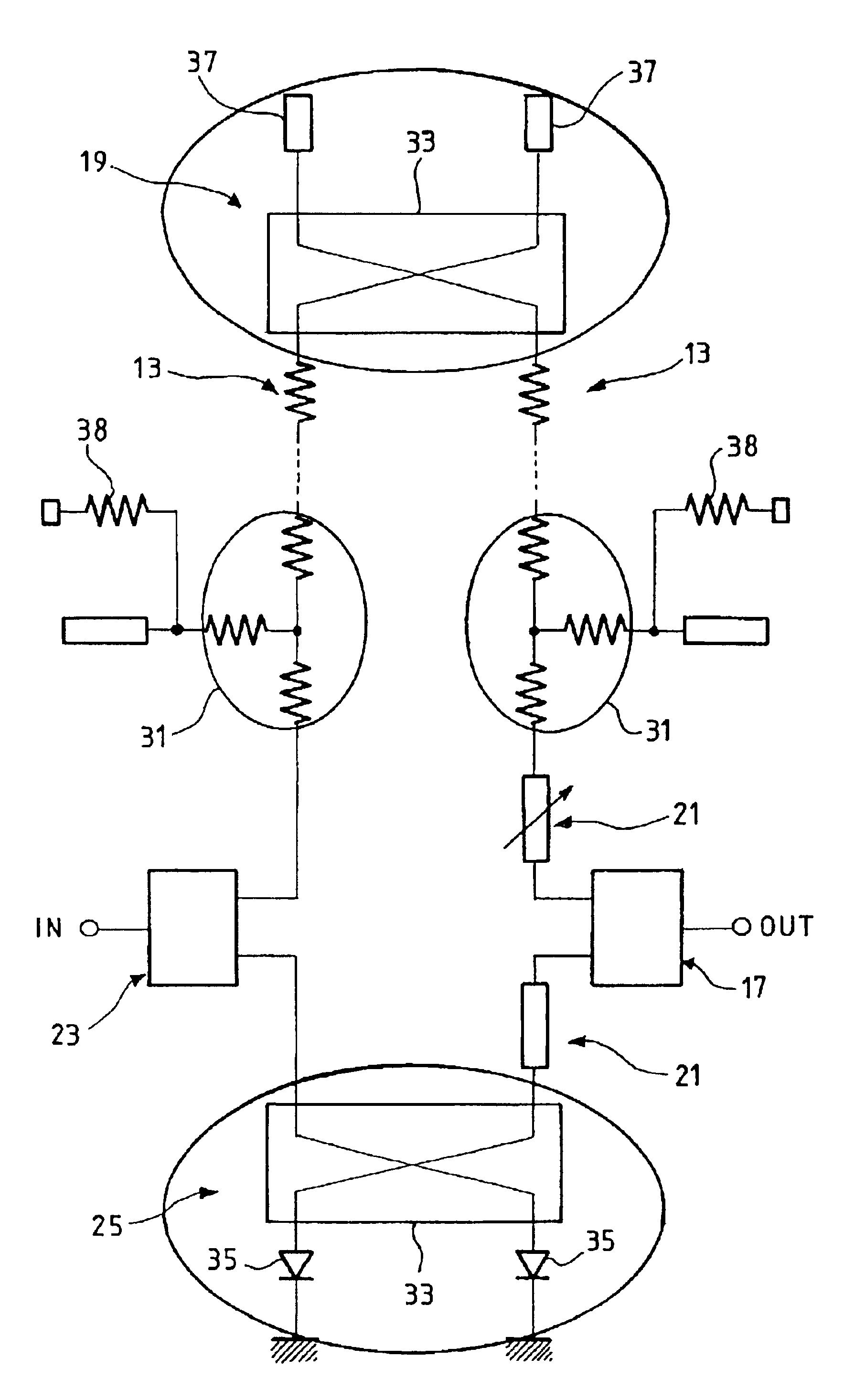
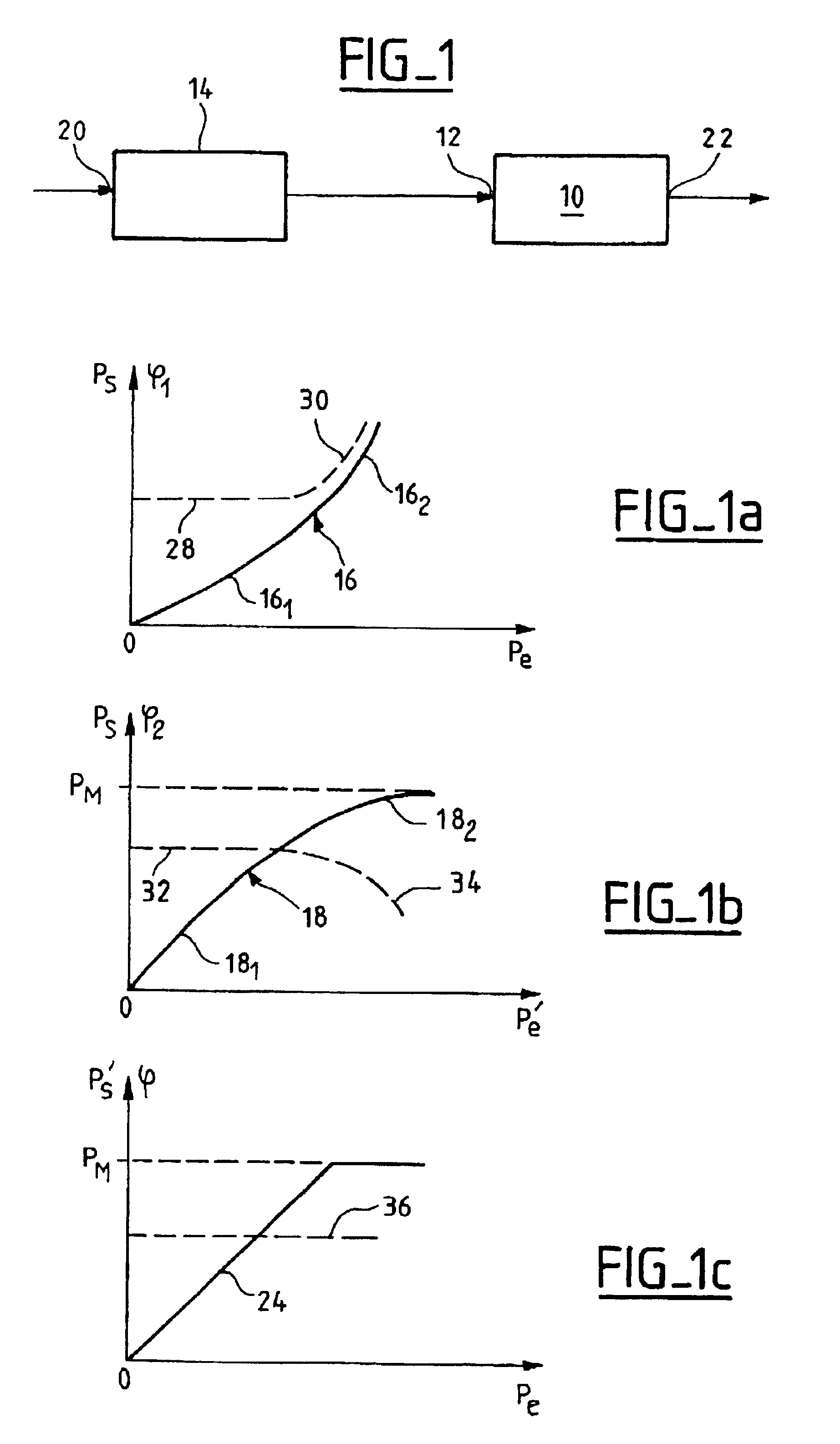
The figures are given as non-limiting examples for illustrating the main characteristics of the invention and its variants. The same references are used to refer to the same elements in the various figures. The figures are not always to scale for reasons of clarity. Equivalent means may be substituted for the elements shown in the figures without thereby going beyond the ambit of the invention.

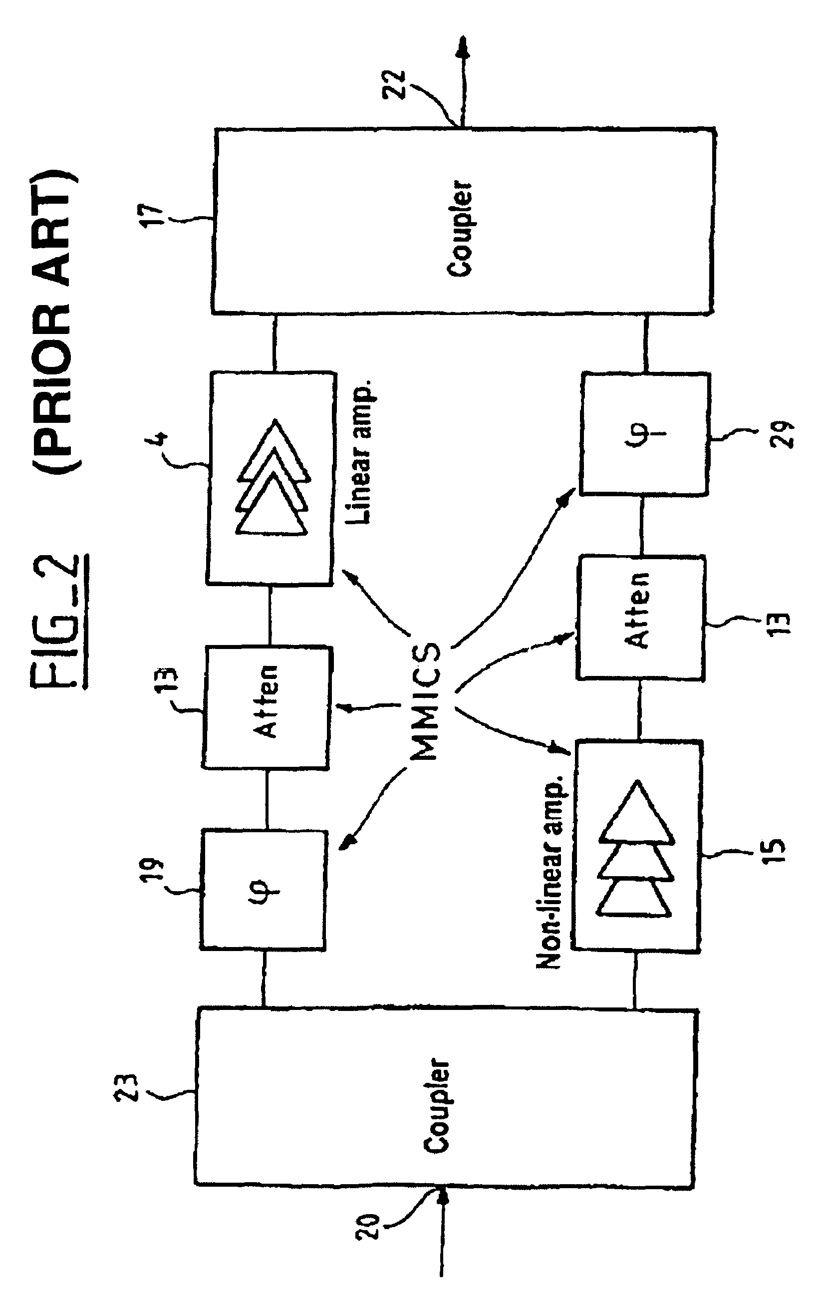
FIG. 2 shows an example of a prior art linearizer. As in the preceding figure, the signal to be amplified is applied to the input 20 of the linearizer, from where it is applied to the input of a power splitting coupler 23. The signal is thus split into two portions, which portions are applied respectively to the inputs of two transmission lines. Conventionally, the coupler / splitter 23 introduces a phase shift e between the two signals it outputs to the two transmission lines. By way of example, the coupler 23 can be a 3 dB hybrid coupler, thus giving rise to a phase shift .theta.=.pi. / 2 (=90.d...


PUM


Abstract

The invention relates to a predistorsion linearizer for a power amplifier operating in the microwave range, the linearizer comprising means for conferring gain and phase predistorsion which compensate the gain and phase non-linearities of the corresponding amplifier, in particular an amplifier of the electronic tube type. The linearizer is characterized in that it comprises: a "linear" first path comprising a Lange coupler having each of its two accesses grounded via a respective passive element, and a "non-linear" second path comprising a Lange coupler having each of its two accesses grounded via a respective active element, the addition of a transmission line of variable length in at least one of the two paths enabling the (non-constant) frequency response of the linearizer to be adjusted in order to compensate the response of the amplifier that is to be linearized.

Description

The invention relates to a predistorsion linearizer for an amplifier having a broad frequency band, in particular in the microwave range.When the power requirements of electronic signals are large, use is made of an amplifier which is caused to operate close to its saturation power. By way of example, mention can be made of the transmission requirements of telecommunications satellites for which traveling wave tube amplifiers are used.Operating the amplifier close to saturation gives it a response that is not linear. More precisely, when the input power is well below saturation power, then output power is substantially proportional to input power. However, as input power comes closer to saturation power, gain decreases, and takes on the value 1 at saturation. This non-linearity also affects the phase of the output signal: phase remains constant when the amplifier is operating away from its saturation zone, but for certain amplifiers (and in particular traveling wave tube amplifiers)...

Claims


Application Information

Patent Timeline
Patent Type & Authority Patents(United States)
IPC IPC(8): H03F3/60H03F1/32
CPCH03F1/3252H03F3/602H03F2200/198
Inventor VILLEMAZET, JEAN-FRAN.CEDILLA.OISMORONI, PASCALCOGO, BERNARD
Owner ALCATEL LUCENT SAS
Why Eureka
Try Eureka