GPS positioning system

a positioning system and positioning system technology, applied in the field of gps, can solve the problems of difficult positioning operation, difficult to know the specific relationship of a positioning point, and difficult to recognize the condition or the like of a positioning operation si

a positioning system and positioning system technology, applied in the field of gps, can solve the problems of difficult positioning operation, difficult to know the specific relationship of a positioning point, and difficult to recognize the condition or the like of a positioning operation si

US6791492B2Inactive Publication Date: 2004-09-14KK TOPCON

Image

  • GPS positioning system
  • GPS positioning system
  • GPS positioning system

Examples


Embodiment Construction

The preferred embodiments of the present invention will be described based on the drawings as follows.

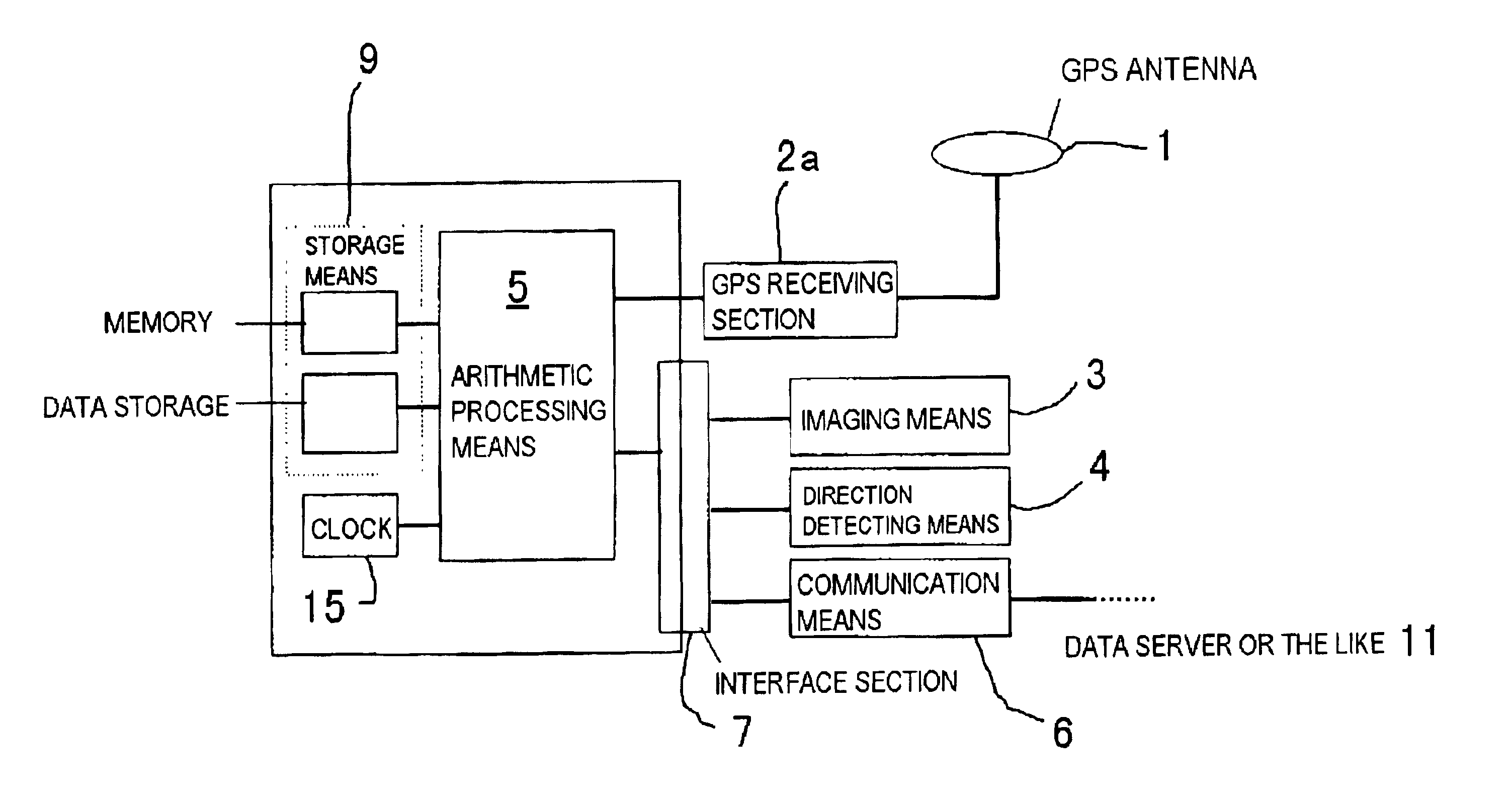
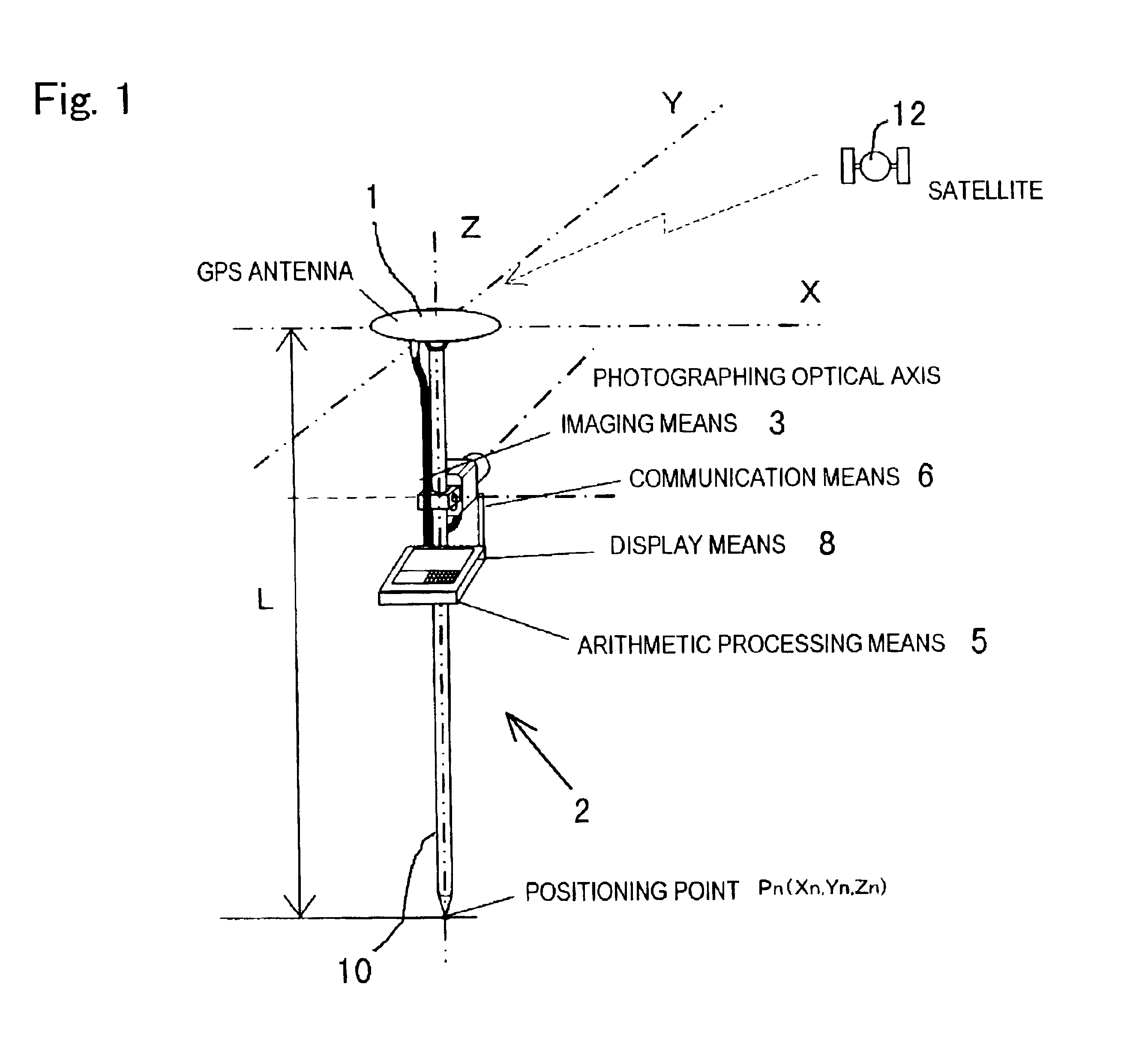
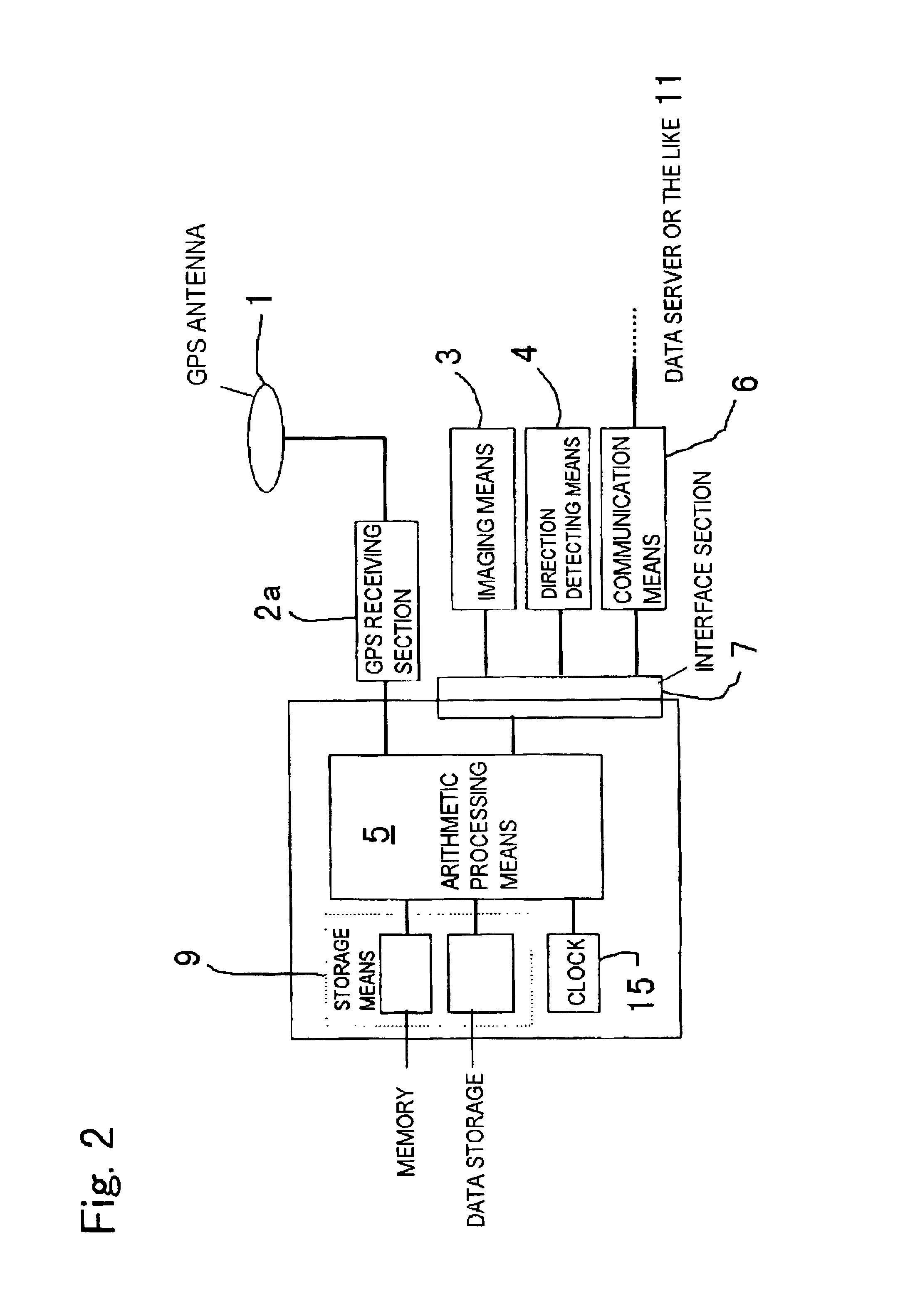
FIGS. 1 and 2 are the external view and the configuration view respectively, showing one embodiment of the GPS positioning system according to the present invention.

The GPS positioning system has: a receiving antenna 1 for GPS and a GPS receiver 2 connected thereto.

Further, the GPS positioning system has: imaging means 3 arranged on a predetermined position for the antenna 1 and capable of photographing arbitrary 360.degree. direction; direction detecting means 4 capable of detecting the photographing direction; arithmetic processing means 5 connected to a GPS receiving section 2a or the imaging means 3; communication means 6 capable of two-way communication with a data server 11; an interface section 7 capable of connecting to the communication means 6; and display means 8 capable of displaying various kinds of information for an operator.

Furthermore, the GPS positioning system has...


PUM


Abstract

A GPS positioning system comprises a fixed station and a mobile station. The mobile station has: positional positioning means; imaging means; direction detecting means; and arithmetic processing means. The positional positioning means measures positional coordinates by receiving radio weve from a satellite. The imaging means is arranged in a predetermined position for the GPS positional positioning means. The direction detecting means detects a photographing direction during photographig by the imaging means. The arithmetic processing means forms landscape data in which imaging data that is an output from the imaging means is associated with orientation data that is an output from the direction detecting means.

Description

1. Technical Field of the InventionThe present invention relates to a GPS (Global Positioning System, which is referred to as a GPS hereinafter) positioning system in which positional coordinates can be found by receiving radio wave from a satellite.2. Prior ArtKinematic positioning in a GPS, when a basic combination of an antenna and a receiver, which is capable of GPS positioning, is defined as a station, is a survey method where a pair of stations arranged on a reference point in a fixed manner are made to be a fixed station, another movable station is made to be a mobile station, positioning is performed while sequentially moving the mobile station among a large number of survey points, and thus finding a relative positional coordinates for the fixed station. Note that the positional coordinates of the reference point are known.There exists a real-time kinematic positioning (hereinafter, referred to as an RTK) as a developed type of the kinematic positioning. This is a positioni...

Claims


Application Information

Patent Timeline
14 Sep 2004
Publication
US6791492B2
IPC
G01C11/00; G01S5/14; G01S19/14; G01S19/43; G01S19/48
CPC
G01C11/00; G01S19/13; G01S19/44; G01S19/51; G01S19/04
Inventors
MIYASAKA, KOJI; MORI, MASAKAZU