Ion generating apparatus

a technology of generating apparatus and ion atomizer, which is applied in the direction of corona discharge, heating type, ventilation system, etc., can solve the problem of dirt adhesion to the needle cathode per se not being prevented at all, lowering the efficiency of ion generation, and more worse discontinuance of ion generation

Inactive Publication Date: 2004-09-14
NIHON PACHINKO PARTS
View PDF13 Cites 37 Cited by
  • Summary
  • Abstract
  • Description
  • Claims
  • Application Information

AI Technical Summary

Benefits of technology

According to the constitution of the present invention, the electric cleaning mechanism is provided to burn out dirt adhered on the ion generating electrode through electric heating, so that the dirt can be removed in a thorough and simple manner, and thus the apparatus can successfully prevent the ion generation efficiency from being degraded due to dirt adhesion. In particular, in case of the ion generating electrode having a sharp end, dirt adhesion to such portion where the ion generating field concentrates will considerably ruin the ion generating efficiency. Burning out of the attachment on the end portion of the ion generating electrode using the electric cleaning mechanism will be extremely beneficial to avoid such nonconformity. In this case, an object of the cleaning will be attained to a sufficient degree if only the dirt adhered onto the sharp end portion of the electrode, which is responsible for the ion generation, is selectively removed, which is also advantageous in simplifying the apparatus since there is no need to excessively raise the electric heating capacity of the electric cleaning mechanism.
The ion generating apparatus of the present invention may have a polarity conversion means for converting the secondary AC output voltage so as to ensure negative predominance of the polarity of voltage applied to the ion generating electrode. The polarity conversion means may be composed of a rectifying means which rectifies secondary AC output from the piezoelectric transformer so as to typically allow charge transfer having a directionality of negatively charging up the ion generating electrode but inhibit charge transfer having an opposite directionality. Further providing a condensing means for condensing negative charge, derived from the secondary AC output of the piezoelectric transformer, to be applied to the ion generating electrode will ensure stable generation of negative ions since the ion generating electrode can constantly be supplied with a negative voltage above a certain level. Combining such condensing means with the foregoing rectifying means will ensure more advanced level of stability in negative high voltage to be applied to the ion generating electrode, which can considerably downsize the apparatus as typically compared with the case of using a specialized high-voltage DC power source.

Problems solved by technology

A problem will however arise in that airborne dust, oil or other dirty matters may adhere onto the ion generating electrode so as to finally cover the discharge plane thereof during a long-term use of such ion generating apparatus.
Once such situation occurs, the discharge for generating ions will badly be interfered, which may result in lowered ion generation efficiency, and more worse discontinuance of the ion generation.
In this prior art, a problem however resides in that the dirt adhesion onto the needle cathode per se cannot be prevented at all.
In particular, in case of the ion generating electrode having a sharp end, dirt adhesion to such portion where the ion generating field concentrates will considerably ruin the ion generating efficiency.
On the other hand, such composition may not always ensure a desirable ion generating efficiency since generated negative ions may be attracted by the counter electrode and may adhere thereon or decompose.

Method used


Image

  • Ion generating apparatus
  • Ion generating apparatus
  • Ion generating apparatus

Examples


Embodiment Construction

Best embodiments for carrying out the present invention will be explained referring to several examples shown in the attached drawings.

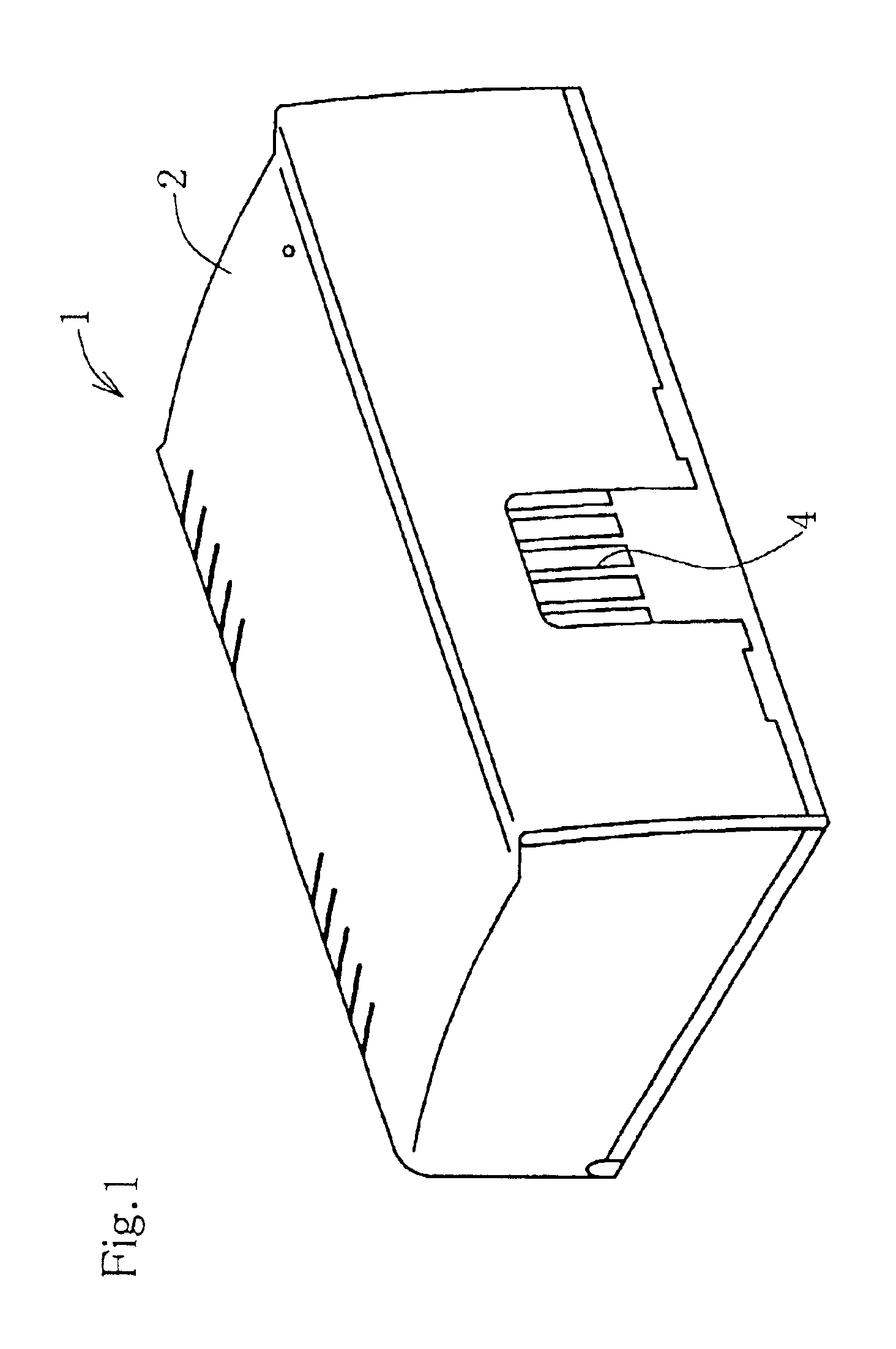
FIG. 1 shows an outer appearance of an ion generating apparatus according to one example of the present invention, where the apparatus has a hollow case 2 as an enclosure composed of a plastic molding. While the shape of the case 2 is not specifically limited, the example shown herein has an axially-elongated and somewhat flattened shape, and has on one lateral plane thereof an ion emitting hole 4. The lateral plane of the case 2 is provided with a power switch 3.

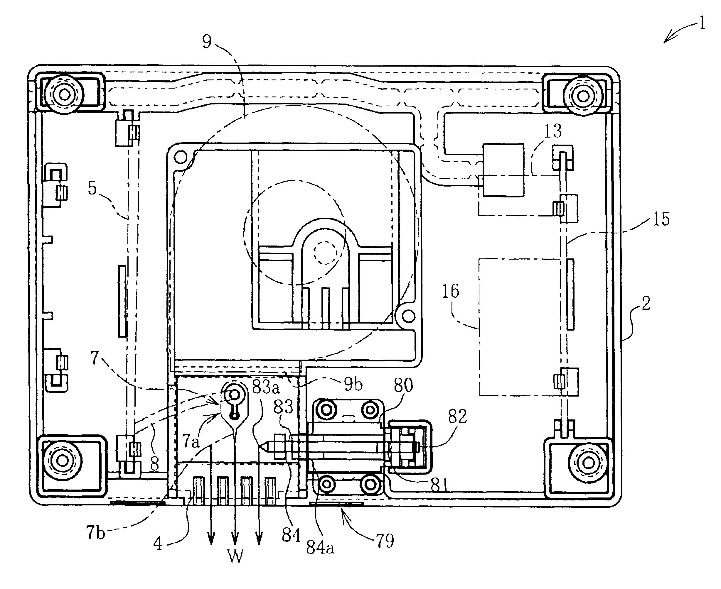
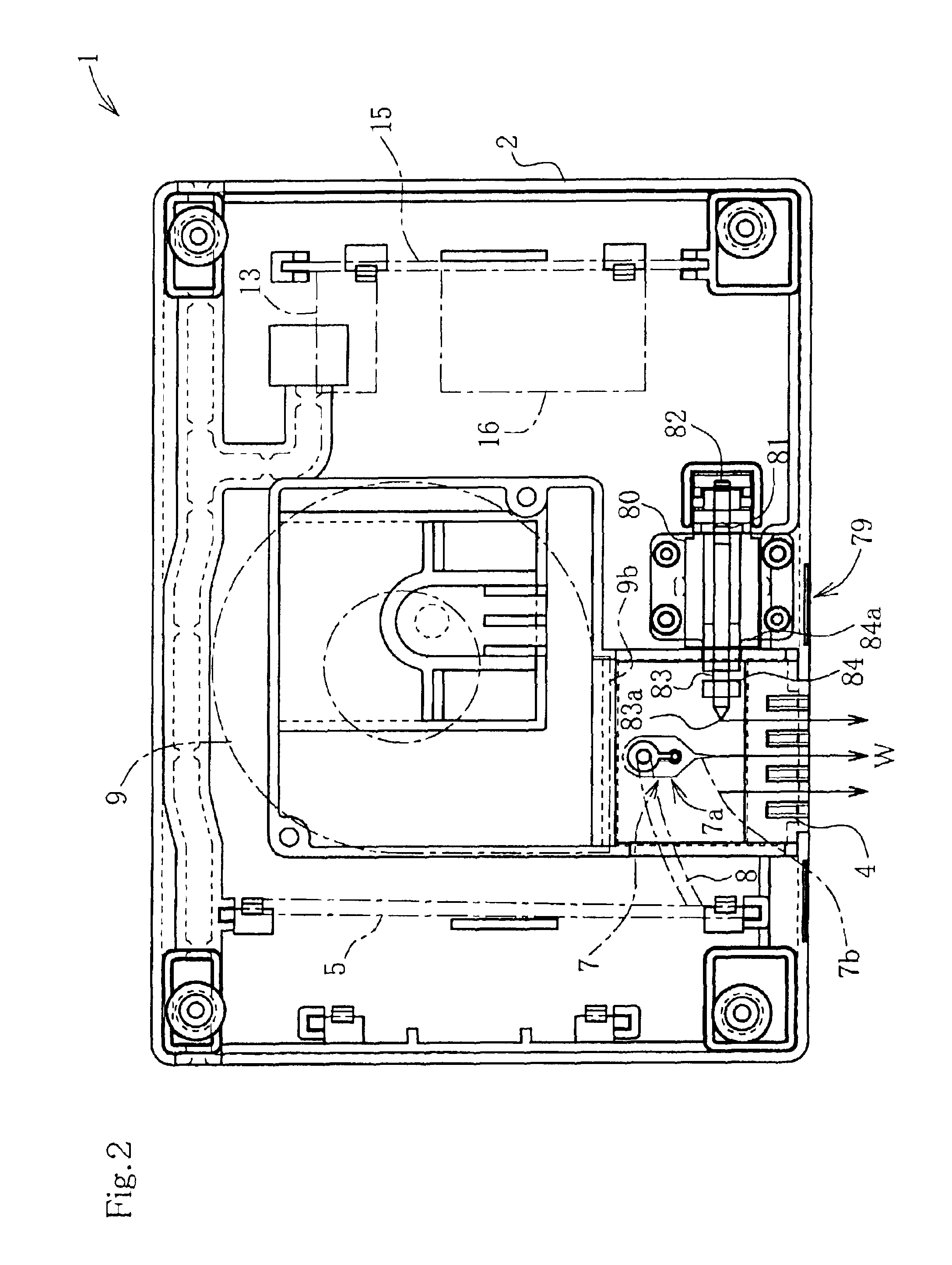
FIG. 2 is a plan sectional view of FIG. 1. An ion generating electrode 7 and a main circuit unit for ion generation 5 are provided within the case 2. The ion generating electrode 7 has a sharpened end made of a metal such as Ni or Ni alloy. In the example shown here, the ion generating electrode 7 has a main body portion 7a and a sharp discharge portion 7b integrated thereto to thereby form ...


PUM

PropertyMeasurementUnit
frequencyaaaaaaaaaa
voltageaaaaaaaaaa
voltageaaaaaaaaaa

Abstract

An ion generating apparatus 1 has an electric cleaning mechanism 79 for burning out attachment adhered on an ion generating electrode 7 by electric heating. Adhesion of dirt and the like onto the end portion of the electrode where an electron generation field concentrates will considerably ruin the ion generation efficiency. So that burning out of attachment adhered onto the end portion 7a of the ion generating electrode 7 using the electric cleaning mechanism 79 is extremely effective in terms of avoiding such nonconformity. Object of the cleaning will be attained to a sufficient degree if only the dirt adhered onto the sharpened end portion of the electrode 7, which is responsible for the ion generation, is selectively removed, which is also advantageous in simplifying the apparatus since there is no need to excessively raise the electric heating capacity of the electric cleaning mechanism 79.

Description

The present invention relates to an ion generating apparatus.DESCRIPTION OF THE BACKGROUND ARTIon generating apparatuses have previously been used for cleaning, disinfection and deodorization of the air in rooms or automobiles. Most of such apparatuses have an AC power source portion, a step-up transformer and a needle electrode, all of which being housed in an enclosure, in which a high AC voltage raised by the transformer is applied to the needle electrode to thereby activate corona discharge, and ions generated by the discharge are emitted from an ion emitting hole opened in the enclosure. Both negative ions and positive ions are possibly generated by the ion generating apparatus, where negative ions are generally believed to be more excellent in cleaning, deodorizing and disinfectant effects.A problem will however arise in that airborne dust, oil or other dirty matters may adhere onto the ion generating electrode so as to finally cover the discharge plane thereof during a long-t...

Claims


Application Information

Patent Timeline
Patent Type & Authority Patents(United States)
IPC IPC(8): H01T23/00A61L9/22B03C3/40B03C3/41B03C3/66B03C3/74B60H3/00F24F7/00H01J17/49H01T19/04H02M3/24
CPCH01T23/00
Inventor ADACHI, YOSHIICHIKATO, YUJI
Owner NIHON PACHINKO PARTS
Why Eureka
Try Eureka