Self-stacking conveyor belt and method

a conveyor belt and self-stacking technology, applied in the direction of conveyors, transportation and packaging, etc., can solve the problems of entire machinery being taken off line at a substantial cost to the operator, fatigue cracks in the welded joints between the side plates and the transverse rods, and the fatigue limit of the welded joints and adjacent areas reached

Inactive Publication Date: 2004-09-28
GEA REFRIGERATION NORTH AMERICA
View PDF15 Cites 9 Cited by
  • Summary
  • Abstract
  • Description
  • Claims
  • Application Information

AI Technical Summary

Benefits of technology

It is another object of the present invention to provide a method for easily modifying existing endless conveyor belts to reduce fatigue cracks.
The improved conveyor belt also includes each transverse rod having at least one bendable section that enables the transverse rod to bend when radial forces are exerted on the top edge of one or both side plates. The addition of an internal buttress-type welded joint between each side plate and at least one of the transverse rod not only strengthens the interconnection of the side plate to the transverse rod but also transfers the stress to the bendable sections on the transverse rods to accommodate deflection of one or both side plates. Both features eliminate fatigue cracks and greatly extend the lifespan of the conveyor belt.

Problems solved by technology

It is well known that during use, fatigue cracks develop in the welded joints between the side plates and the transverse rods.
When cracks are detected or when the conveyor belt breaks, the entire machinery must be taken off line at a substantial cost to the operator.
Eventually, the fatigue limits of the welded joints and adjacent areas are reached and cracks are formed.
Unfortunately, these changes increases the overall weight of the conveyor belt which places higher loads on the drive and support system and limit the amount of product that can be carried.
Heretofore, the formation of fatigue cracks has not been alleviated.

Method used


Image

  • Self-stacking conveyor belt and method
  • Self-stacking conveyor belt and method
  • Self-stacking conveyor belt and method

Examples


Embodiment Construction

)

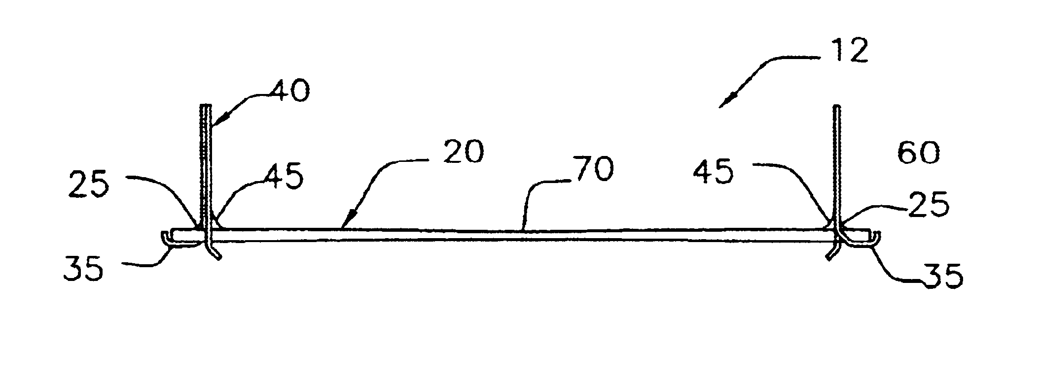
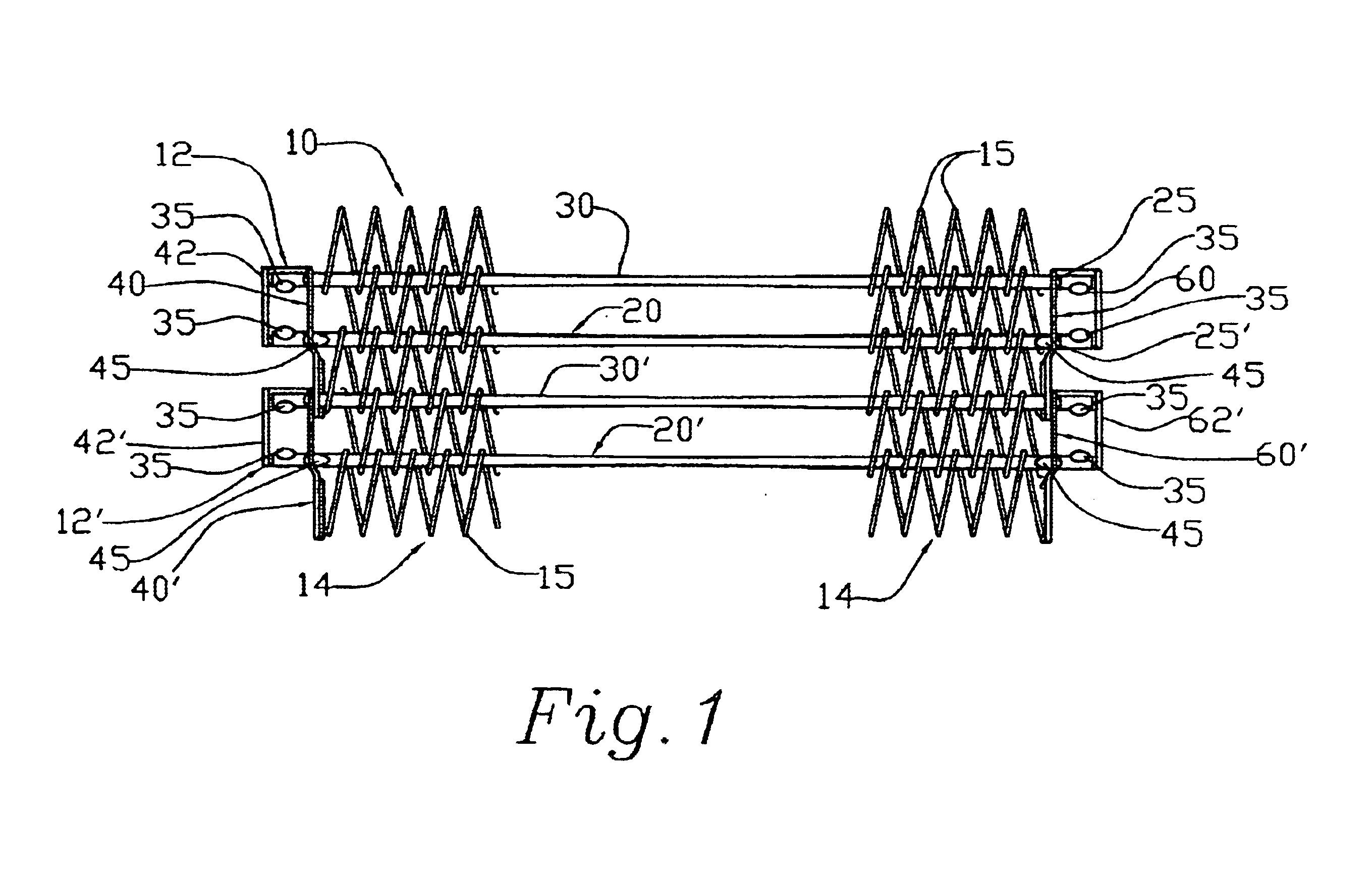
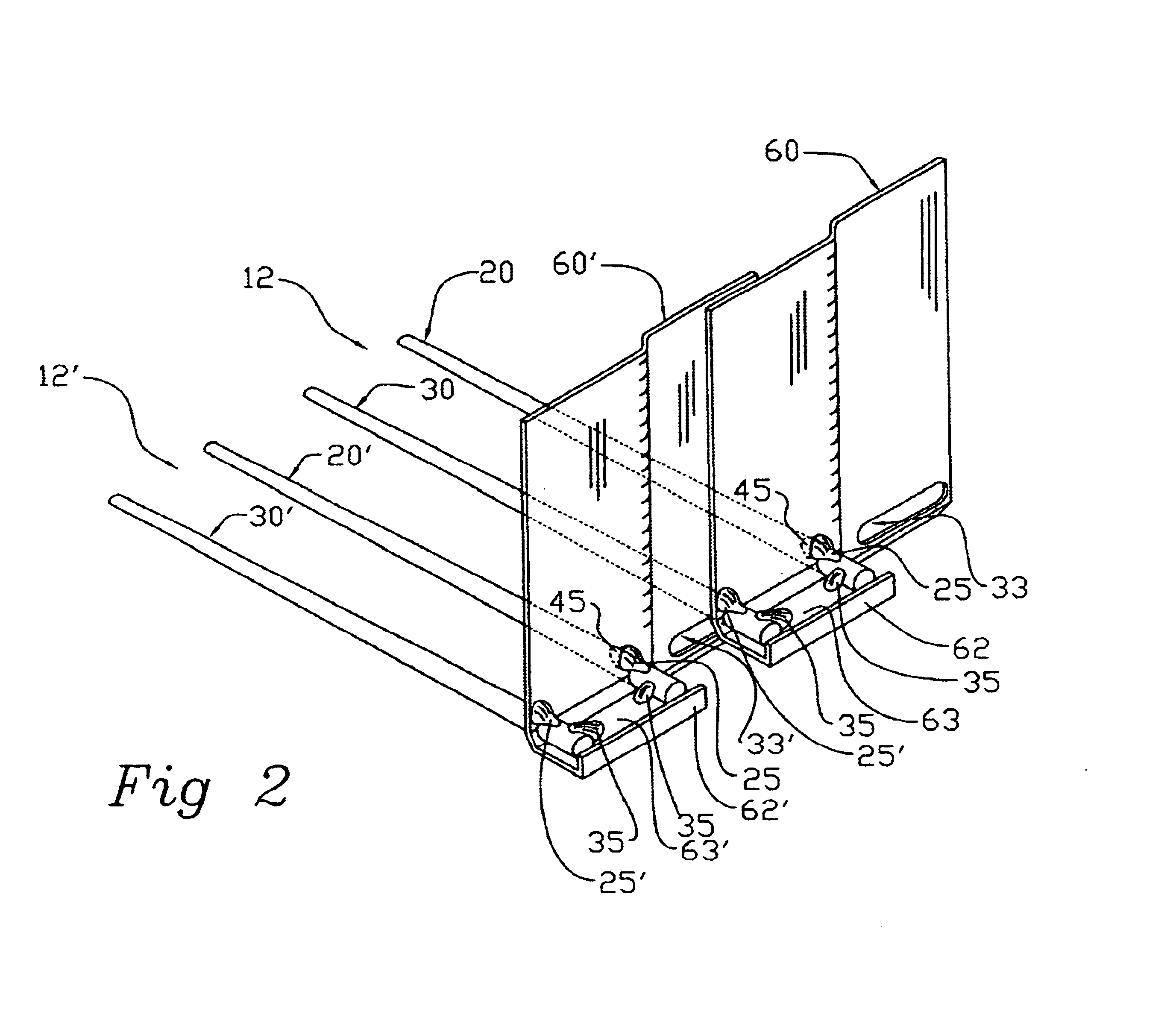
There is shown in FIG. 1 an improved endless self-stacking conveyor belt 10, similar to the conveyor belts disclosed in U.S. Pat. Nos. 4,603,776, 4,941,567 5,190,143 and 5,803,232 and incorporated by reference herein. The conveyor belt 10 includes a plurality of transversely aligned interlocked links, 12, 12'. Each link 12, 12' includes two traverse rods 20, 30, 20', 30' and two vertically aligned side plates 40, 40', 60, 60 ' rigidly connected to the opposite ends of the two transverse rods 20, 30, 20', 30', respectively. A flexible mesh 14 made of a plurality of small loop structures 15 that individually wrap around adjacent transverse rods 20, 30 is disposed between the side plates 40, 40', 60, 60 ' and used support products on the conveyor belt 10. The conveyor belt 10 disclosed herein is specifically designed to overcome the development of fatigue cracks between transverse rods 20, 30 and the two side plates 40, 60 on each link 12, 12' caused by repeated cyclical stress on the...


PUM


Abstract

An improved endless conveyor belt made of a plurality of interconnected links, each including two rods with two side plates perpendicularly aligned and attached to their opposite ends. The improvement comprising the addition of an internal buttress-type welded joint located between the inside surface of each side plate and one or both transverse rods with at least one bendable section. During use, the transverse rod is allowed to bend so that the side plates may deflect when force is exerted on them. By adding the welded joint and by adding the bendable section to the transverse rod, the number of cracks or breaks in the conveyor belt is substantially reduced.

Description

1. Field of the InventionThe invention pertains to conveyor belts commonly used for the freezing and cooking of foods and other processing applications, and more precisely to improvements that make such belts more resistant to fatigue cracks.2. Description of the Related ArtEndless, self-stacking conveyor belts used in the freezing and cooking food industries are described in U.S. Pat. Nos. 4,603,776, 4,941,567, 5,190,143 and 5,803,232. Such conveyor belts comprise a plurality of interconnected links, each including two transverse rods and a pair of upward extending side plates. The two transverse rods are parallel and horizontally aligned and extend through holes formed near the lower edge of each side plate. Formed on one-half of the each plate is a laterally extending foot over which the ends of the two transverse rods extend. Formed on the other one-half of each side plate is an elongated slot through which one of the transverse rods from an adjacent link extends. During assembl...

Claims


Application Information

Patent Timeline
Patent Type & Authority Patents(United States)
IPC IPC(8): B65G17/08B65G17/06
CPCB65G17/064B65G17/086B65G21/18B65G2201/02
Inventor BYRNE, RICHARD K.HEBER, GERALD J.
Owner GEA REFRIGERATION NORTH AMERICA
Why Eureka
Try Eureka