Power-supply device

a power supply device and power supply technology, applied in the direction of dc-dc conversion, climate sustainability, power conversion systems, etc., can solve the problems of difficult stabilization of the control loop, inability to expect the damping of the esr, and inability to completely make the power supply device small

Inactive Publication Date: 2004-09-28
GOOGLE LLC
View PDF9 Cites 48 Cited by
  • Summary
  • Abstract
  • Description
  • Claims
  • Application Information

AI Technical Summary

Problems solved by technology

The component constants of the CR smoothing filter are a capacitance of 0.47 .mu.F and a resistance of 100 .OMEGA.. Accordingly, the CR smoothing filter having such constants cannot be formed on chip in a power supply IC and must be formed externally of the IC chip, resulting in a problem that the power supply device cannot be made in small size totally.
This makes it impossible to expect the damping of the ESR as is expected in the case of using the aluminum electrolytic capacitor.
Consequently, it becomes difficult to stabilize the control loop.
In the above-described prior art, when using the ceramic capacitor with the small ESR as the power LC smoothing filter, it becomes impossible to expect the damping effect of the ESR.
This causes a signal to oscillate, thereby making the phase compensation difficult.
Also, if, in the prior art, it were to become possible to implement the phase compensation by narrowing the operation bandwidth of the error amplifier, a response from the power-supply is delayed exceedingly.
Moreover, in modifying the LC smoothing filter's constants, there exists a troublesome task of adjusting the phase compensation condition of the error amplifier on each that occasion.

Method used


Image

  • Power-supply device
  • Power-supply device
  • Power-supply device

Examples


embodiment 1

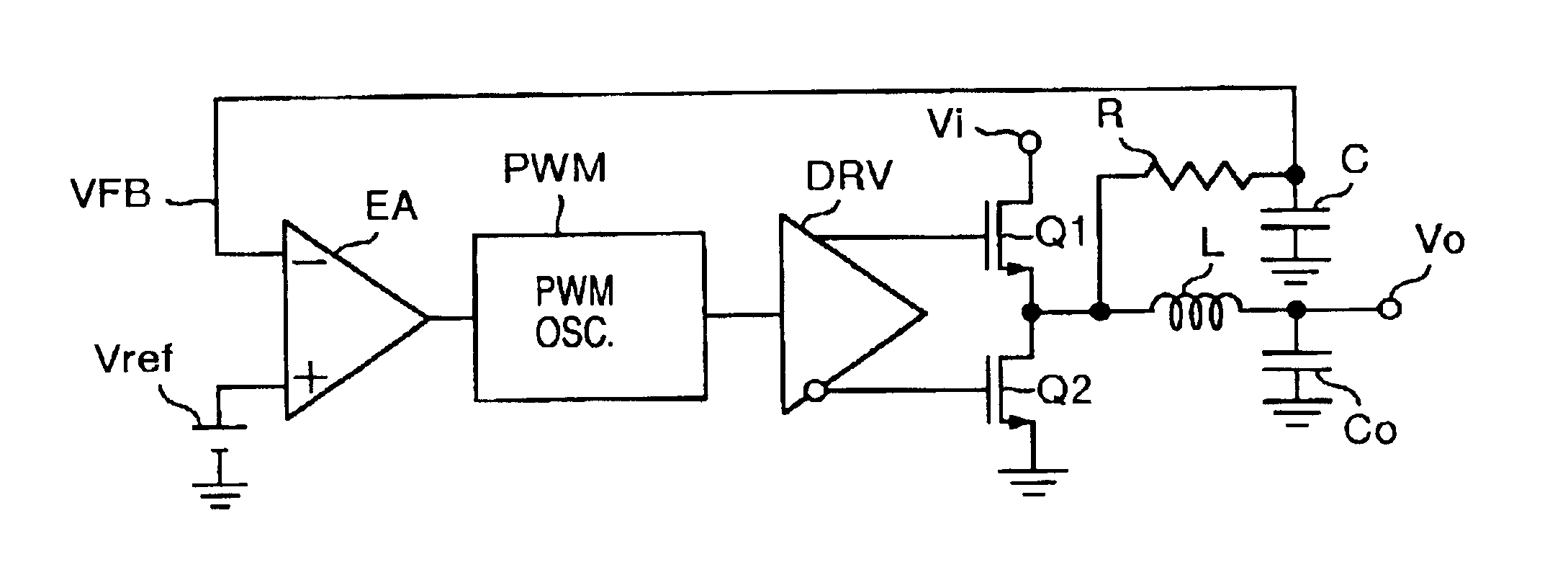
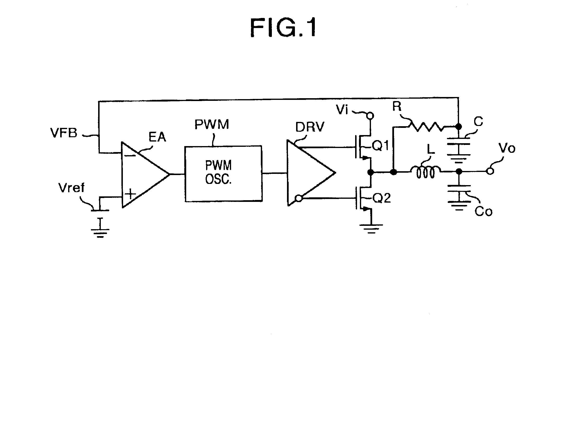
FIG. 1 illustrates a power-supply device of the present embodiment. In FIG. 1, reference notations Vi and Vo denote an input terminal and an output terminal, respectively. An upper-side Power MOSFET Q1 is connected to the input terminal Vi, and a lower-side Power MOSFET Q2 is connected to a ground potential side. An LC smoothing filter, i.e., a power output filter consisting of an inductor L and a capacitor Co, and a CR smoothing filter consisting of a resistor R and a capacitor C are connected in parallel to a midpoint of the Power MOSFETs Q1 and Q2. Moreover, the output terminal Vo is connected to a midpoint of the LC smoothing filter, and one input (-) of an error amplifier EA is connected to a midpoint of the CR smoothing filter. Here, the capacitor Co of the LC smoothing filter is a chip ceramic capacitor.

Also, a reference voltage Vref is connected to the other input (+) of the error amplifier EA. A pulse-width modulation (abbreviated as PWM) oscillator PWM, and gates of the Po...

embodiment 2

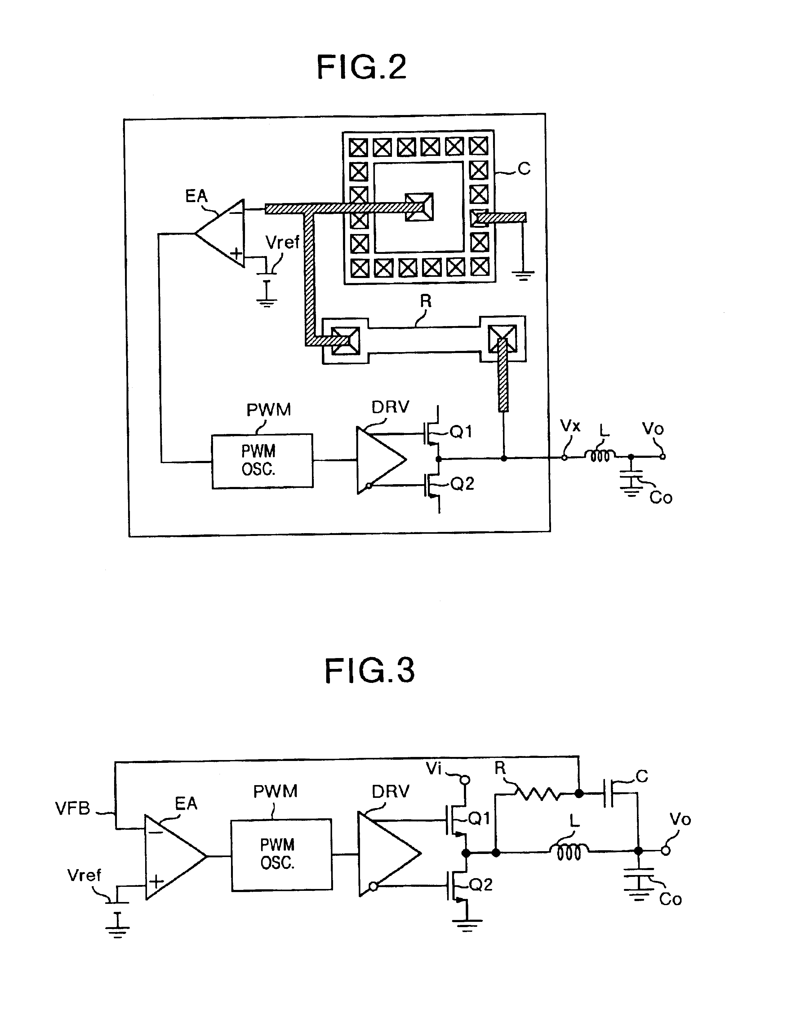
FIG. 3 illustrates the present embodiment. In FIG. 3, the same reference notations are attached to the same configuration components in FIG. 1. The point in which FIG. 3 differs from FIG. 1 is that the CR smoothing filter is set up at both ends of the inductor L of the LC smoothing filter. In the present embodiment, since the electrostatic capacitance of the capacitor Co of the output LC smoothing filter is large, the inductor-connected edge side of the capacitor Co can also be regarded as the ground potential. The present embodiment also allows the acquisition of basically the same effects in FIG. 1. Furthermore, the present embodiment makes it possible to perform the negative feedback of an infinitesimal capacitance change caused by a temperature change in the capacitor Co of the LC smoothing filter. Consequently, even if the chip ceramic capacitor with a small ESR is used, the present embodiment permits an enhancement in the stability of the control loop. In this case as well, th...

embodiment 3

FIG. 5 illustrates a power-supply device obtained by further providing a transient variation detecting circuit TVD into the 1st embodiment. This transient variation detecting circuit TVD controls the duty of the pulse-width modulation oscillator PWM by detecting a transient load variation between the output voltage Vout at the output terminal Vo and a voltage that results from adding a upper and lower limit-voltage width .+-..DELTA. to the reference voltage Vref. FIG. 6 illustrates a concrete example of the pulse-width modulation oscillator PWM and that of the transient variation detecting circuit TVD.

In FIG. 6, the pulse-width modulation oscillator PWM is a variable oscillator including a voltage-to-current converting circuit V / I, current-source MOSs 110, 120, inverters INV11, INV12, a capacitor 105, and a flip-flop FF. Also, the transient variation detecting circuit TVD includes comparators CMP1, CMP2, switching MOSs SW1 to SW4, constant current-sources I1 to I4, and inverters INV...


PUM


Abstract

A step-down type DC-DC power-supply device implements both the stabilization of the control loop and the responsibility at the same time. In the power-supply device, an output power signal is fed back to an error amplifier after having passed through a CR smoothing filter provided independently of a power LC smoothing filter. Also, independently of the duty controls over Power MOSFETs, i.e., upper-side / lower-side semiconductor switching components in the steady state, an output from the power LC smoothing filter is added to an upper and lower limit-mode-equipped control circuit, thereby, at the transient state, forcefully setting the duty alpha at either 0% or 100%.

Description

1. Field of the InventionThe present invention relates to a power-supply device where, independently of a power LC smoothing filter, a signal is caused to pass through a CR smoothing filter and is then fed back so that the control loop will be stabilized.2. Description of the Related ArtA prior art on the loop stabilizing method for a power-supply device has been described in "Low-Voltage On-Board DC / DC Modules for Next Generations of Data Processing Circuits", Zhang et al., IEEE Tran. on Power Elect. Vol. 11, No. 2, March 1996. In the power-supply device according to the prior art, a signal is fed back to an error amplifier from a power LC smoothing filter. Then, the error amplifier compensates the phase, thereby implementing the stabilization of the control loop. In this prior art, an aluminum electrolytic capacitor is used as the power LC smoothing filter.U.S. Pat. No. 5,877,611 discloses a power supply system in which an output of a CR smoothing filter connected across an induct...

Claims


Application Information

Patent Timeline
Patent Type & Authority Patents(United States)
IPC IPC(8): H02M3/158H02M3/335H02M3/04H02M3/24
CPCH02M3/1584H02M3/1588H02M3/33507Y02B70/1466Y02B70/10
Inventor SASE, TAKASHITATENO, KOJIKANOUDA, AKIHIKOHAYASHI, KATSUNORIYOSHIDA, SHINICHI
Owner GOOGLE LLC
Why Eureka
Try Eureka