Magnetic disk apparatus and method of controlling the same

a magnetic disk and apparatus technology, applied in the direction of maintaining the head carrier alignment, recording information storage, instruments, etc., can solve the problems of durability and reliability declin

Inactive Publication Date: 2004-09-28
HITACHI GLOBAL STORAGE TECH JAPAN LTD
View PDF11 Cites 46 Cited by
  • Summary
  • Abstract
  • Description
  • Claims
  • Application Information

AI Technical Summary

Benefits of technology

With the use of the method above, it is possible to achieve a low flotation amount corresponding to the required high recording density irrespective of machining variations of the individual magnetic head slider and in-use environments including, but not limited to atmospheric pressure differences while at the same time making it possible to prevent any possible continuous physical contact between the magnetic head slider and magnetic disk, resulting in preclusion of contact vibration and / or thermal asperity. This in turn enables improvement in linear recording density and thus further increases in storage capacities of the magnetic disk apparatus while further miniaturizing or downsizing the magnetic disk apparatus.
With use of the method, it is possible to shorten a response time with respect to a read / write command, which in turn makes it possible to lessen the frequency of contact between the record / reproduction element and magnetic disk while at the same time significantly reducing the length of a read / write time duration. This enables reduction of wear otherwise occurring due to physical contact between the record / reproduction element and magnetic disk.
The magnetic disk apparatus control method of the invention is the one wherein the proper shift amount estimation processing is done when the magnetic head slider is at an outer periphery of the magnetic disk and also done when it is at inner periphery thereof respectively for one time for storing resultant proper shift amounts at the outer periphery and the inner periphery in memories respectively while in the ordinary read / write events performing linear interpolation of the proper shift amounts at the outer periphery and the inner periphery in accordance with a position in a radial direction along the diameter whereat the magnetic head slider presently resides to thereby calculate a proper shift amount at the position thus permitting the record / reproduction element to shift accordingly.
Using the method makes it possible to accurately calculate an adequate or proper shift amount of the magnetic head slider at any given positions along the diameter of such magnetic disk while significantly shortening both a time as required for the proper shift amount estimation processing and a time period of contact between the record / reproduction element and the magnetic disk due to the same processing.
Using the method makes it possible to accurately calculate the proper shift amount of the magnetic head slider at any given radial position along the diameter of the magnetic disk while simultaneously enabling significant reduction of both a time as taken to perform estimation processing of such proper shift amount(s) and a contact time duration for contact between the record / reproduction element and the magnetic disk due to the same processing.
With the method, in case where contaminants are deposited on the record / reproduction element during long-term operation resulting in a decrease in intensity of the magnetic disk's magnetic information playback signal, the proper shift amount estimation processing is done thereby making it possible to remove away such contamination at the record / reproduction element section, which in turn enables achievement of long-term operabilities of the magnetic disk apparatus while reducing or minimizing complexities in maintenance thereof.

Problems solved by technology

Unfortunately, with the active head slider scheme as taught from the above-identified former Japanese citation JP-A-62-250570, it is required in order to attain the required high record density to further shrink the distance between the record / reproduction element and the magnetic disk, although the scheme offers enhanced effectivities for reduction of the distance between the record / reproduction element and magnetic disk.
As per the method for detecting a resistance change occurring due to a temperature variation upon contacting, i.e. thermal asperity, independently of ordinary magnetic data read / write operations as suggested by the latter document JP-A-10-233070, this method is encountered with a risk of frequent occurrence of intermittent physical contact due to microconfiguration on the magnetic disk side and on the magnetic head slider side, causing a serious problem as to likewise decreases in durability and reliability.

Method used


Image

  • Magnetic disk apparatus and method of controlling the same
  • Magnetic disk apparatus and method of controlling the same
  • Magnetic disk apparatus and method of controlling the same

Examples


Embodiment Construction

One preferred embodiment of the present invention will now be set forth in detail with reference to the accompanying drawings of FIGS. 1 to 5 below.

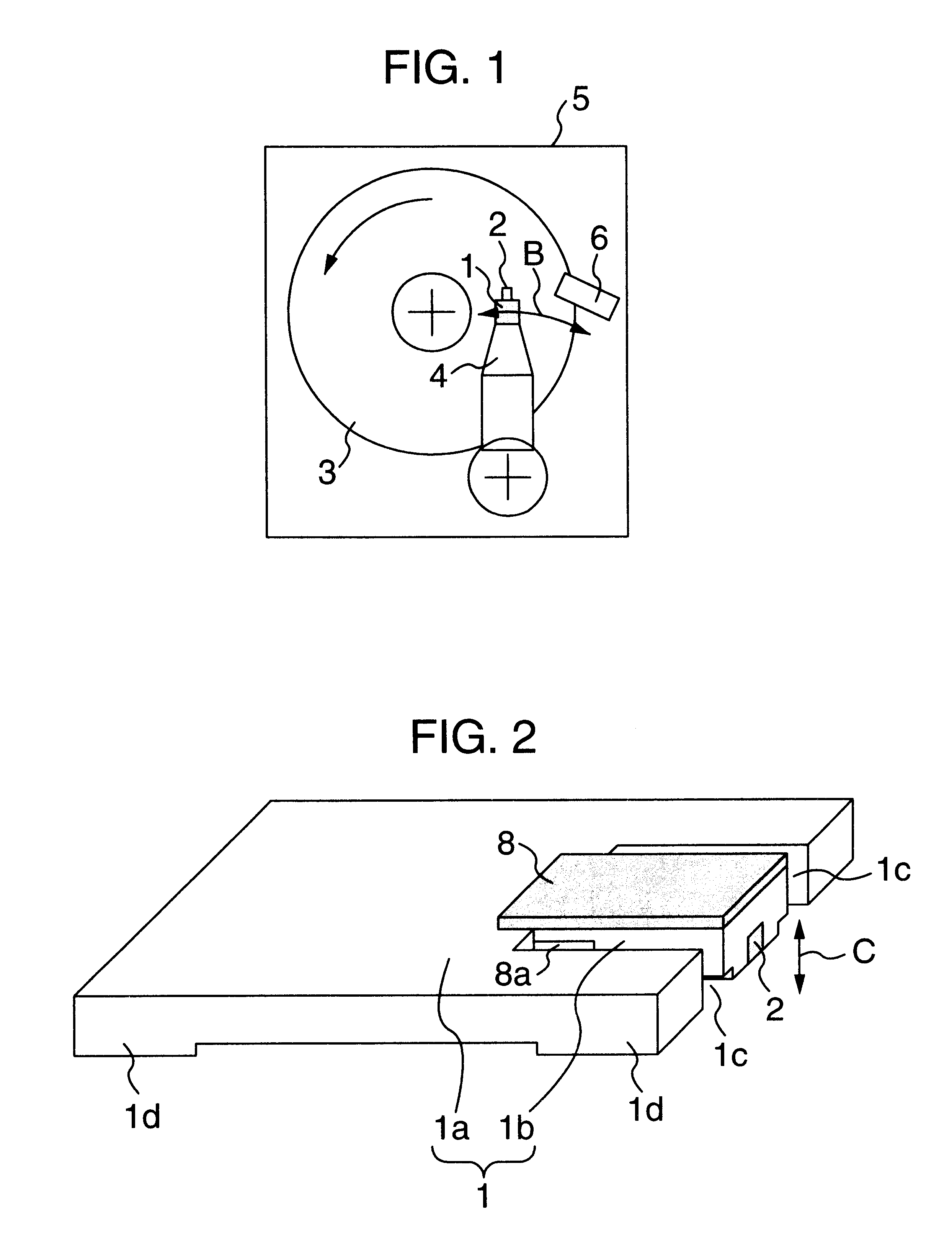
FIG. 1 shows schematically an overall arrangement of a magnetic disk apparatus embodying the invention. In this drawing, reference numeral is used to designate a magnetic head slider with a built-in recording / reproduction element 2 for recording and reproducing (read / write) magnetic information; numeral 3 denotes a magnetic disk that stores therein magnetic information and is driven by a rotation mechanism, not shown, to rotate or spin in a direction indicated by arrow; 4 indicates a load beam which is formed of a plate-like flat spring member for performing position determination of the magnetic head slider 1 in a radial direction along the diameter of the magnetic disk 3 while applying a compressive force to displace or bias it toward the magnetic disk 3; and 5 is a ramp which permits the magnetic head slider 1 to move for safety from ...


PUM

PropertyMeasurementUnit
thicknessaaaaaaaaaa
thicknessaaaaaaaaaa
lengthaaaaaaaaaa

Abstract

A magnetic disk apparatus includes a rotation mechanism for driving a magnetic disk, a magnetic head slider being floated in close proximity to a surface of the magnetic disk, a recording / reproduction element for performing recording and playback of information, a drive unit for causing a distance between the record / reproduction element and the magnetic disk to change, and means for performing position determination of the magnetic head slider, wherein the apparatus has a detection unit for permitting the drive unit to gradually reduce the distance between the record / reproduction element and the magnetic disk and for detecting occurrence of contact therebetween, and a control unit for controlling the drive unit in such a way as to cause, the record / reproduction element to shift in position by a fixed amount to thereby let the distance between this element and magnetic disk increase accordingly.

Description

1. Field of the InventionThe present invention relates to magnetic disk apparatus with high-density magnetic information recording performances and control methodology thereof.2. Description of the Related ArtConventionally known magnetic disk apparatus adaptable for use as external storage devices or else of computers are typically designed to include a rotation mechanism for driving more than one magnetic disk to rotate or spin at high speeds, and a magnetic head slider with a built-in recording / reproduction element. The magnetic head slider is supported by a load beam so that it is position-determined and placed along the diameter of the magnetic disk. The magnetic disk apparatus is arranged to record magnetic information at a desired track(s) on the magnetic disk and also reproduce such stored magnetic information out of the magnetic disk while letting the magnetic head slider relatively move over the magnetic disk. The magnetic head slider is designed to use an air lubrication ...

Claims


Application Information

Patent Timeline
Patent Type & Authority Patents(United States)
IPC IPC(8): G11B21/21G11B5/60G11B5/56G11B5/54G11B5/58G11B5/48
CPCG11B5/6005G11B21/21G11B5/4886G11B5/54G11B5/56G11B5/581
Inventor KURITA, MASAYUKIMATSUMOTO, MASAAKIOOTANI, YUUICHIMIYAKE, YOSHIHIKOHIGUCHI, SHINSUKETANAKA, HIDEAKIXU, JUNGUO
Owner HITACHI GLOBAL STORAGE TECH JAPAN LTD
Why Eureka
Try Eureka