High speed driving method and apparatus of pressure cylinder

a technology of high-speed driving and pressure cylinder, which is applied in the direction of resistance electrode holders, servomotors, manufacturing tools, etc., can solve the problems of affecting largely the working efficiency and unnecessarily long operation tim

Inactive Publication Date: 2004-10-05
SMC CORP
View PDF6 Cites 21 Cited by
  • Summary
  • Abstract
  • Description
  • Claims
  • Application Information

AI Technical Summary

Benefits of technology

In the driving method of the invention, it is preferable that a speed in the vicinity of an end of the forward stroke of the piston rod is reduced by cushion effect caused by limiting a flow rate of exhaust gas from a rod-side pressure chamber. With this, a tip end of the piston rod can touch a work softly.
When the cushion effect functions, an internal pressure in the rod-side pressure chamber becomes lower than an internal pressure in ahead-side pressure chamber, this acts as a trigger to actuate a quick exhaust valve, the quick exhaust valve directly opens the rod-side pressure chamber into atmosphere to abruptly lower a back pressure of the piston, so that time required until a maximum pressurizing force can be generated by the piston rod is shortened.
The pressure cylinder may comprise a cushion mechanism for reducing a speed of the piston rod in the vicinity of the end of the forward stroke of the piston rod, thereby limiting a flow rate of exhaust gas from the rod-side pressure chamber.
According to the invention having the above structure, the intermediate stopping position of the piston rod can arbitrarily be set by a signal input to the control apparatus from outside. Therefore, if an intermediate stopping position is previously obtained in accordance with a shape of a work and the intermediate stopping position is input as a designated position successively, it is possible to prevent a waste from being generated in stroke.
Further, as described above, since the state in which substantially the same pressures are applied to the pressure chambers formed on the opposite sides of the piston is maintained when the piston rod is returned to the intermediate stopping position, when a projecting stroke is started, it is unnecessary to fill the pressure chamber whose pressure is completely lowered to the atmospheric pressure with compressed air, and it is only necessary to add pressure fluid of necessary amount for previously added pressure fluid. Therefore, there is no driving delay unlike the conventional case in which a pressure chamber is driven by a switching valve, time required for projecting stroke can be shortened and thus, operation efficiency can be enhanced.

Problems solved by technology

As a result, wasteful stroke is generated in accordance with a work shape in some cases and in such a case, there is a problem that the operation time unnecessarily becomes long.
Therefore, it takes time to supply pressure, and the driving operation of the pressure cylinder is delayed correspondingly, and this largely affects the working efficiency.
The above-described problem is seen not only in the spot welding gun cylinder, but also in a device in which a head mounted to a tip end of a piston rod is repeatedly pushed against a work such as a pressure unit of various clamp device, and such a case also has the same problem.

Method used


Image

  • High speed driving method and apparatus of pressure cylinder
  • High speed driving method and apparatus of pressure cylinder
  • High speed driving method and apparatus of pressure cylinder

Examples


first embodiment

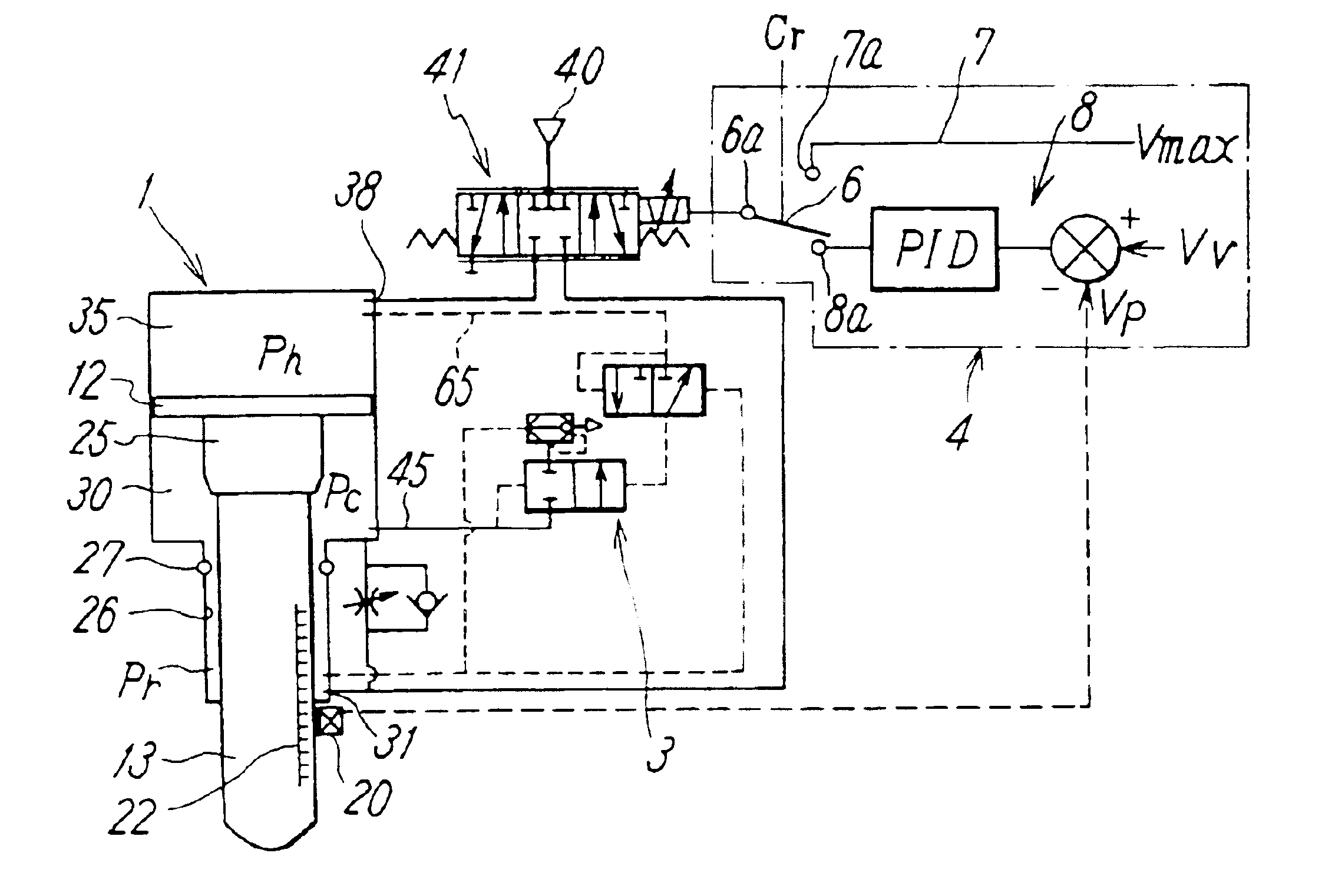
FIG. 2 shows the high speed driving apparatus for actuating the pressure cylinder 1. In this high speed driving apparatus, the supply / discharge port 38 which is in communication with the head-side pressure chamber 35 of the cylinder 1 and the supply / discharge port 31 which is in communication with the rod-side pressure chamber 30 are connected to a servo valve 41, and an air pressure source 40 is connected to the servo valve 41. A detection signal from the position detector 20 is fed back to the control section 4 which controls the servo valve 41.

The servo valve 41 has a first communication position in which the supply / discharge port 38 is connected to the air pressure source 40 and the supply / discharge port 31 is opened into atmosphere, a second communication position in which the supply / discharge port 38 is opened into the atmosphere and the supply / discharge port 31 and the air pressure source 40 are connected to each other, and a neutral position in which both the supply / discharg...

second embodiment

FIG. 6 shows the present invention. The second embodiment corresponds to the first embodiment except that the quick exhaust valve 3 of the high speed driving apparatus is omitted. Since the high speed driving apparatus of this embodiment does not have the quick exhaust valve 3, time required from an instant when the cushion mechanism functions to an instant when the maximum pressurizing force is obtained becomes longer than that in the first embodiment. The second embodiment may be employed in accordance with kind of operation carried out by the piston rod 13 or properties of a work. The cushion mechanism may be omitted if necessary. Other structure and effect are the same as those in the first embodiment and thus, essential portions are designated with the same symbols and explanation thereof is omitted to avoid redundancy.

As described above, according to the present invention, there are provided a driving method and a driving apparatus in which a totally returning position and an ...


PUM

PropertyMeasurementUnit
speedaaaaaaaaaa
pressuresaaaaaaaaaa
internal pressureaaaaaaaaaa

Abstract

A pressure cylinder is connected to an air pressure source through a servo valve, the servo valve is controlled as an on / off switching valve by a control section in an advancing working step of a piston rod, and at the time of backward stroke of the piston rod, an operation position of the piston rod is detected by a position detector to feedback a detection signal to the control section, the servo valve is controlled by the control section such that a deviation between the operation position and a preset stopping position is eliminated, the piston rod is stopped at an intermediate stopping position, and a state in which substantially the same pressures are supplied to pressure chambers formed on opposite sides of the piston is maintained.

Description

TECHINICAL FIELDThe present invention relates to high speed driving method and mechanism of a pressure cylinder which is suitably utilized when a work is pressurized at an end of a stroke like a gun cylinder for spot welding.RELATED ARTA movable-side electrode driven by a gun cylinder for spot welding is opposed to a work on a stationary-side electrode through a relatively short working stroke, and it is required that spot welding is carried out plural times in minimal time while deviating welding positions.To satisfy such a requirement, in Japanese Patent Application No.2001-49020 proposed by the present inventors, a mechanism for setting an intermediate stopping position of a piston is provided so that the piston can be stopped at an intermediate position. A totally returning position to which a work moves to the opposed position of a piston rod and an operation preparing position (intermediate stopping position) to which the piston rod is allowed to be opposed to the work through...

Claims


Application Information

Patent Timeline
Patent Type & Authority Patents(United States)
IPC IPC(8): B23K11/31B23K11/30F15B11/046F15B11/00F15B11/048F15B9/09F15B9/00B23K11/11F15B15/22B23K11/24F15B11/06F15B11/15
CPCB23K11/315F15B11/046F15B11/048F15B15/223F15B9/09F15B2211/7653F15B2211/30525F15B2211/327F15B2211/40515F15B2211/40584F15B2211/41536F15B2211/473F15B2211/6054F15B2211/6336F15B2211/6654F15B2211/75F15B2211/6656F15B2211/6658F15B21/087F15B21/082
Inventor YO, SEIKAIFUJIWARA, NOBUHIROMATSUMOTO, DAISUKE
Owner SMC CORP
Why Eureka
Try Eureka