Supercharge Your Innovation With Domain-Expert AI Agents!

Reduced current input buffer circuit

a buffer circuit and current reduction technology, applied in the direction of power consumption reduction, pulse technique, instruments, etc., can solve the problems of slow performance characteristics of input buffers designed to conserve power, designers are faced with steadily decreasing power consumption requirements, and input buffers optimized for performance (high speed) typically consume much more power

Inactive Publication Date: 2004-10-05
ROUND ROCK RES LLC
View PDF33 Cites 28 Cited by
  • Summary
  • Abstract
  • Description
  • Claims
  • Application Information

AI Technical Summary

Benefits of technology

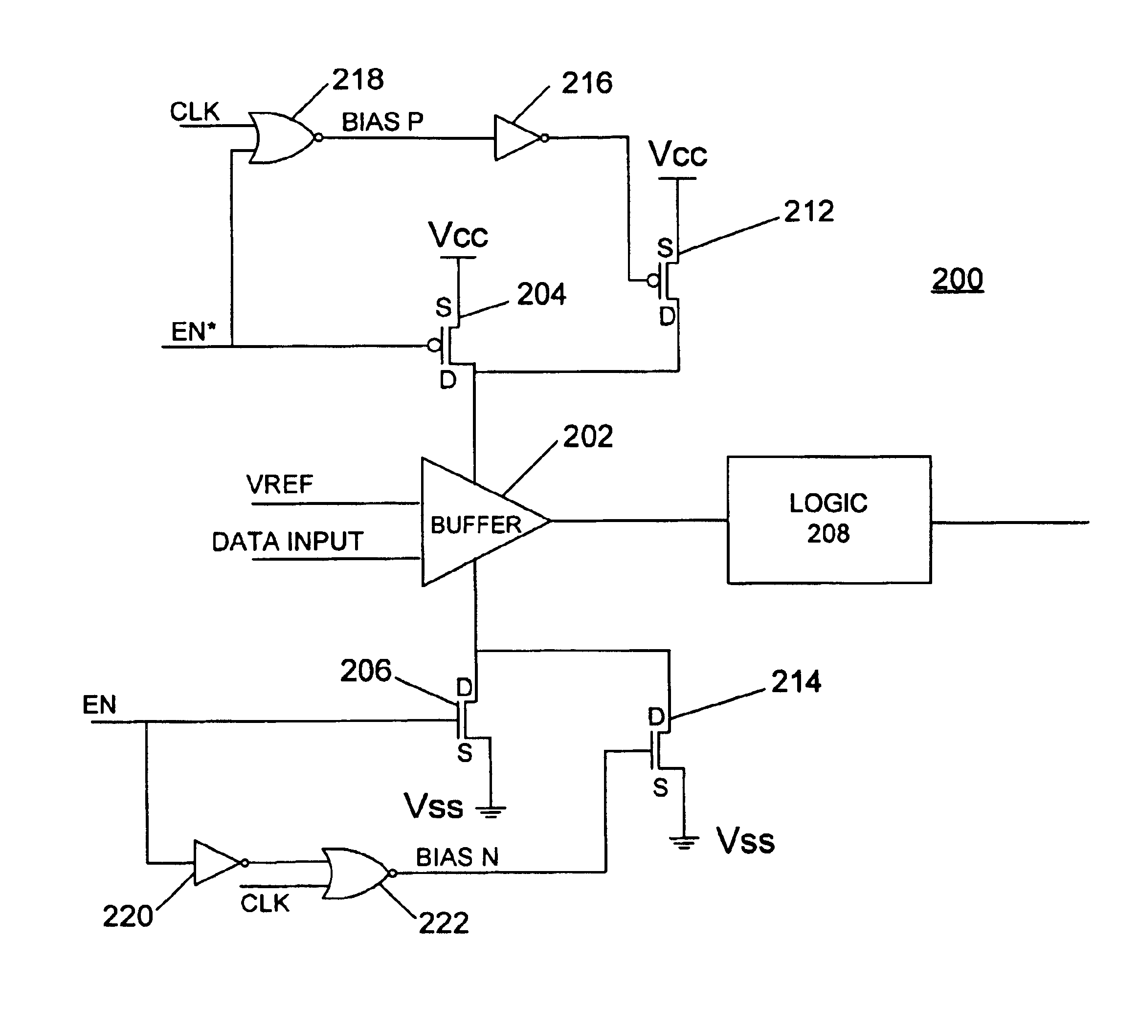
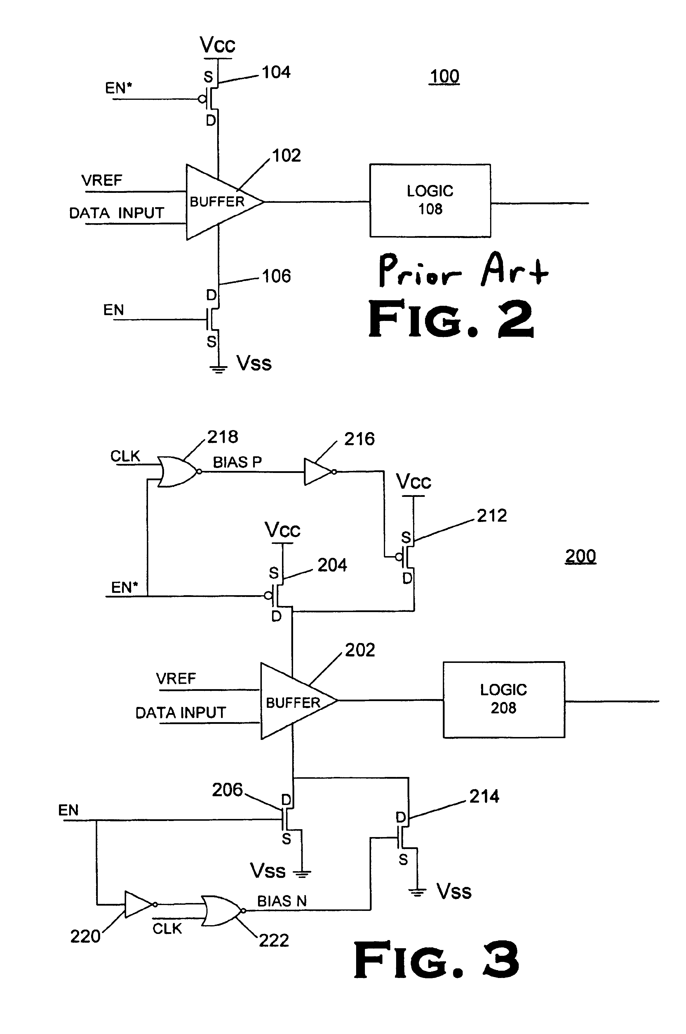
"The present invention relates to an input buffer circuit that achieves high performance with reduced power consumption. The technical effect of the invention is to provide an input buffer circuit that offers relatively high performance in terms of operational speed but consumes less power. This is achieved by providing an input buffer that is designed to draw an operating current and includes first and second buffer enabling circuitry that provides current to the input buffer if it is expecting data. Turning off the input buffer when it is not in use can result in slowed down or lost data, so the invention provides a solution to this problem by allowing the input buffer to remain powered on when not in use and only turn on when the clock signal is low, reducing power consumption without sacrificing performance."

Problems solved by technology

This means that an input buffer that is optimized for performance (high speed) typically consumes much more power than an input buffer designed to save power.
Correspondingly, an input buffer that is designed to conserve power typically has slower performance characteristics compared to an input buffer that is designed for high performance.
Unfortunately, designers are also faced with steadily decreasing power consumption requirements.
Power consumption goals are being driven down because users of computers and other electronic devices that incorporate integrated circuits are demanding increasingly small package sizes and longer battery life.
There is, however, a problem with turning the input buffers completely off when the CLOCK signal is high.
The problem is that input buffers take time to get ready when power is reapplied to them.
If the buffer is not ready when the next successive data input comes in, then the speed at which the incoming data transfers through the input buffer may slow down or incoming data may be lost altogether.

Method used


Image

  • Reduced current input buffer circuit
  • Reduced current input buffer circuit
  • Reduced current input buffer circuit

Examples


Embodiment Construction

One or more specific embodiments of the present invention will be described below. In an effort to provide a concise description of these embodiments, not all features of an actual implementation are described in the specification. It should be appreciated that in the development of any such actual implementation, as in any engineering or design project, numerous implementation-specific decisions must be made to achieve the developers' specific goals, such as compliance with system-related and business-related constraints, which may vary from one implementation to another. Moreover, it should be appreciated that such a development effort might be complex and time consuming, but would nevertheless be a routine undertaking of design, fabrication, and manufacture for those of ordinary skill having the benefit of this disclosure.

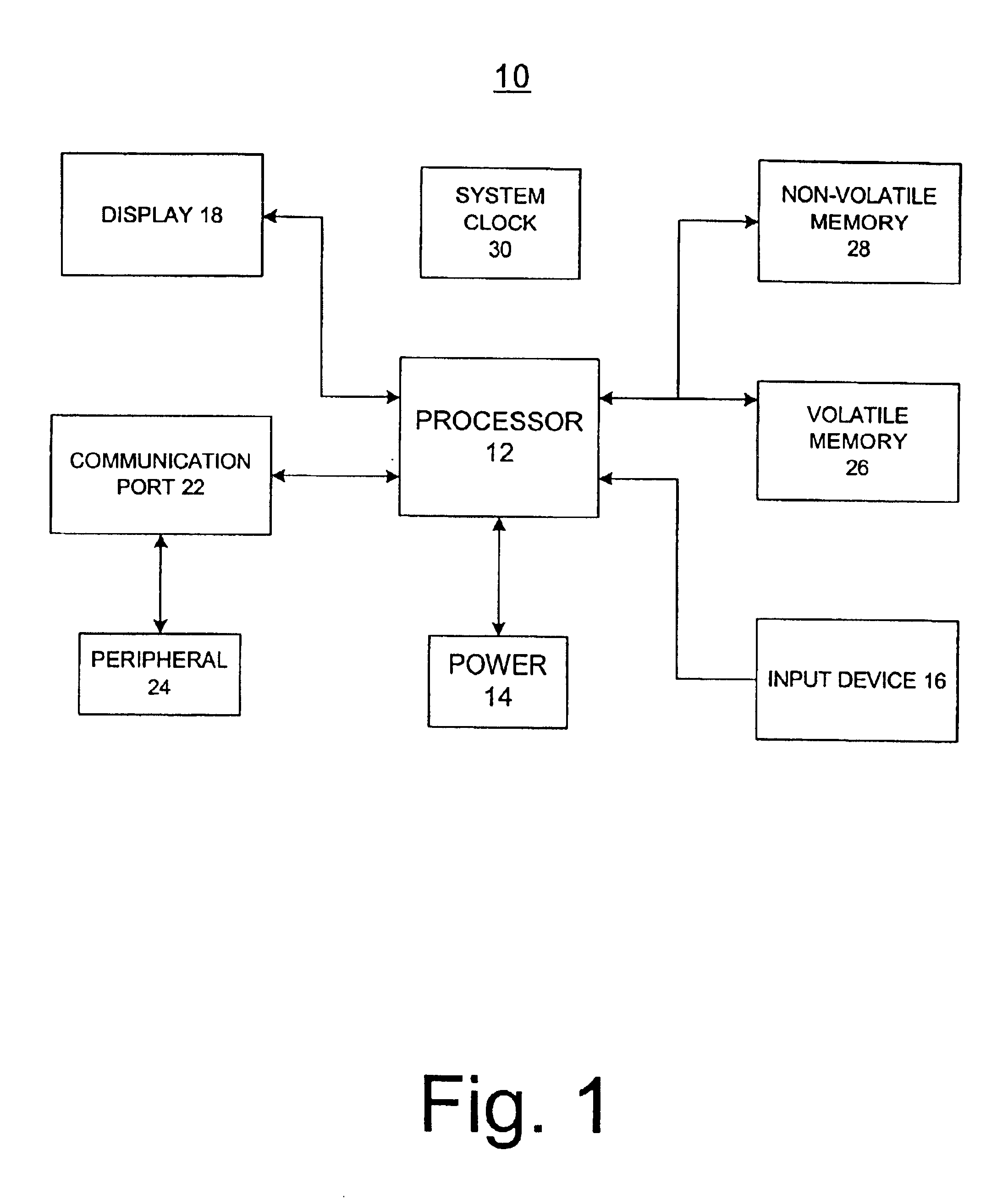
Turning now to the drawings, FIG. 1 is a block diagram depicting an exemplary processor-based electronic device, generally designated by the reference numeral 1...


PUM


Abstract

A differential input buffer circuit includes enabling circuitry that provides a first portion of an operating current to an input buffer. Enabling circuitry provides a second portion of the operating current when data is expected. A process may be used in an input buffer that is adapted to draw an operating current. Such a process comprises the acts of providing a first portion of the operating current to the input buffer and providing a second portion of the operating current to the input buffer if the input buffer is expecting data.

Description

1. Field of the InventionThis present invention relates generally to the field of integrated circuit design and, more specifically, to an input buffer circuit that achieves high performance with reduced power consumption.2. Description of the Related ArtThis section is intended to introduce the reader to various aspects of art that may be related to various aspects of the present invention, which are described and / or claimed below. This discussion is believed to be helpful in providing the reader with background information to facilitate a better understanding of the various aspects of the present invention. Accordingly, it should be understood that these statements are to be read in this light, and not as admissions of prior art.Computer systems and other electronic devices typically include a variety of electrically interconnected integrated circuit (IC) packages which perform a variety of functions, including memory and processing functions. Many integrated circuit devices have i...

Claims


Application Information

Patent Timeline
Patent Type & Authority Patents(United States)
IPC IPC(8): H03K19/00
CPCH03K19/0016
Inventor COWLES, TIMOTHY B.
Owner ROUND ROCK RES LLC
Features
  • R&D
  • Intellectual Property
  • Life Sciences
  • Materials
  • Tech Scout
  • Unparalleled Data Quality
  • Higher Quality Content
  • 60% Fewer Hallucinations
Learn More