

Rack mountable computer component fan cooling arrangement and method
a computer component and rack mount technology, applied in the direction of liquid fuel engine components, dc source parallel operation, non-positive displacement fluid engines, etc., can solve the problems of waste of back plane space and fan exhaust plenum, time-consuming replacement, and individual fans mounted in each component. to achieve the effect of facilitating the rearward re-direction of air flow
- Summary
- Abstract
- Description
- Claims
- Application Information
AI Technical Summary
Benefits of technology
Problems solved by technology
Method used
Image

Examples
Embodiment Construction
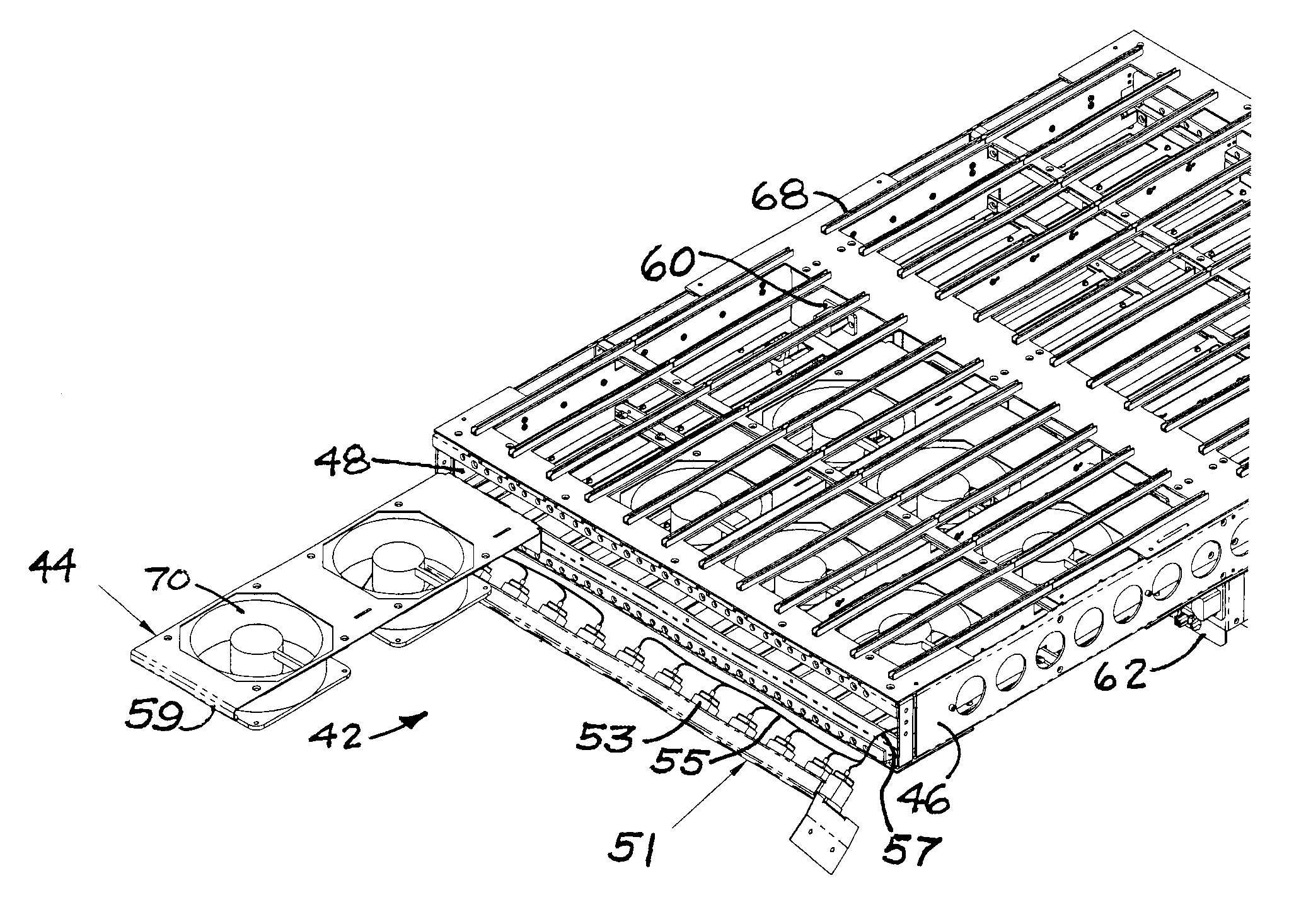
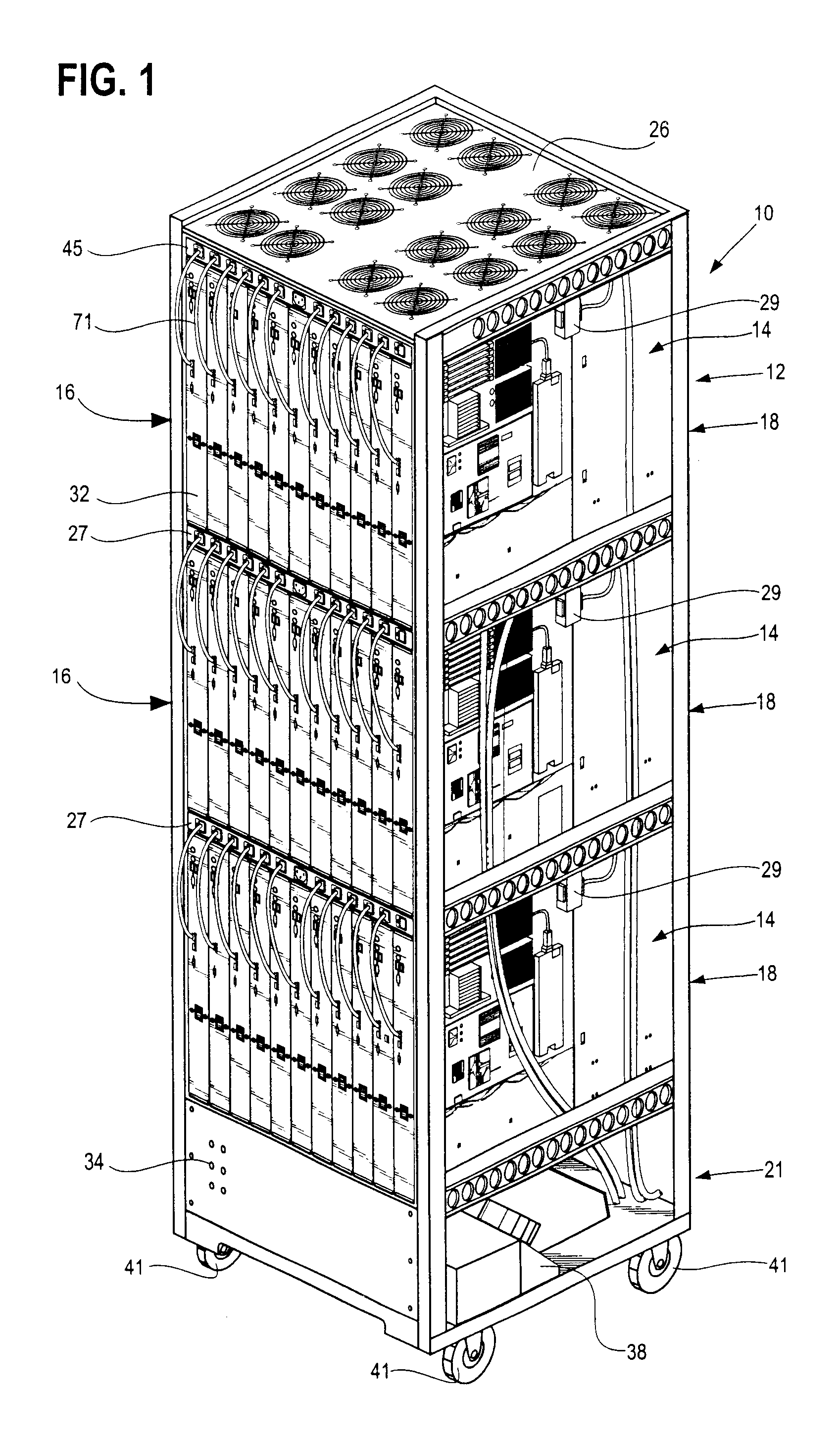
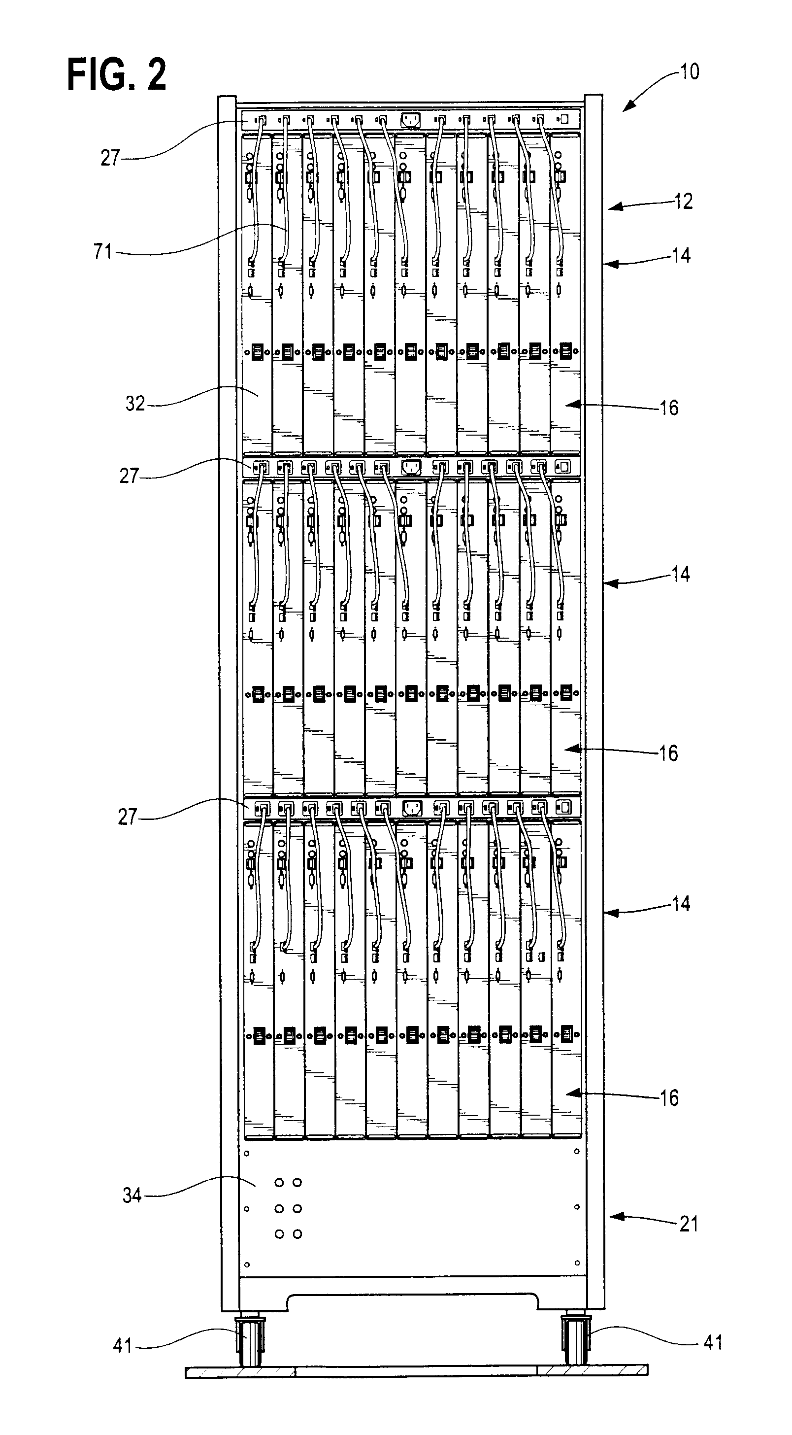
According to certain embodiments of the invention, there is provided an arrangement for cooling a series of closely spaced upright computer components mounted to a support, the arrangement including a tray having a plurality of air moving devices such as fans. Members are used for helping mount removably the tray to the support in a generally horizontal disposition, and the air moving devices move air in a generally upright path of travel to help cool the upright computer components. The tray also has a series of connector ports for connecting electrically to outputs from individual ones of the computer components.
According to the other embodiments of the invention, the tray includes a front panel having the connector ports arranged in a row thereon. As disclosed herein, the front panel can be opened to permit access to the air moving devices or removing them for repair or replacement. The air moving devices can be removed from the support as a unit. Also, as disclosed herein, accor...
PUM
 Abstract
Description
Claims
Application Information