Lasing semiconductor optical amplifier with output power monitor and control

a technology of semiconductor optical amplifier and output power monitor, which is applied in the direction of semiconductor lasers, laser optical resonator construction, laser details, etc., can solve the problems of degrading the corresponding signal-to-noise ratio, attenuating the optical signal, and stretching the network capacity to its limi

Inactive Publication Date: 2004-10-05
II VI DELAWARE INC
View PDF23 Cites 40 Cited by
  • Summary
  • Abstract
  • Description
  • Claims
  • Application Information

AI Technical Summary

Problems solved by technology

Due to this demand, network capacities are being stretched to their limit.
In these systems, phenomena such as fiber losses, losses due to insertion of components in the transmission path, and splitting of the optical signal may attenuate the optical signal and degrade the corresponding signal-to-noise ratio as the optical signal propagates through the communications system.
Saturation occurs when an optical amplifier is unable to sufficiently amplify an optical signal to a desired power level that is above the amplifier's power saturation level.
Saturation occurs when an active region within an SOA is unable to effectively amplify at least one channel within the optical signal.
This failure is caused by insufficient powe...

Method used


Image

  • Lasing semiconductor optical amplifier with output power monitor and control
  • Lasing semiconductor optical amplifier with output power monitor and control
  • Lasing semiconductor optical amplifier with output power monitor and control

Examples


embodiment 500

The active region 504 in embodiment 500 includes a double heterostructure (DH) of p-InAlAs / I-InAlGaAs / n-InAlAs. In other embodiments, the active region 504 may comprise a multiple quantum well (MQW) active region. MQW structures include several quantum wells and quantum wells have the advantage of enabling the formation of lasers with relatively low threshold currents. Both double heterostructures and quantum wells may be fabricated using various materials systems, including for example InAlGaAs on InP substrates, InGaAsP on InP, GaInNAs on GaAs, InGaAs on ternary substrates, and GaAsSb on GaAs. An embodiment uses InAlGaAs grown on an InP substrate. GaAs, InGaAs, or InAlGaAs on GaAs; or nitride material systems may also be suitable. Alternatively, the active region 504 may comprise a single quantum well.

The choice of materials system will depend in part on the wavelength of the optical signal to be amplified, which in turn will depend on the application. Wavelengths in the approxima...

second embodiment

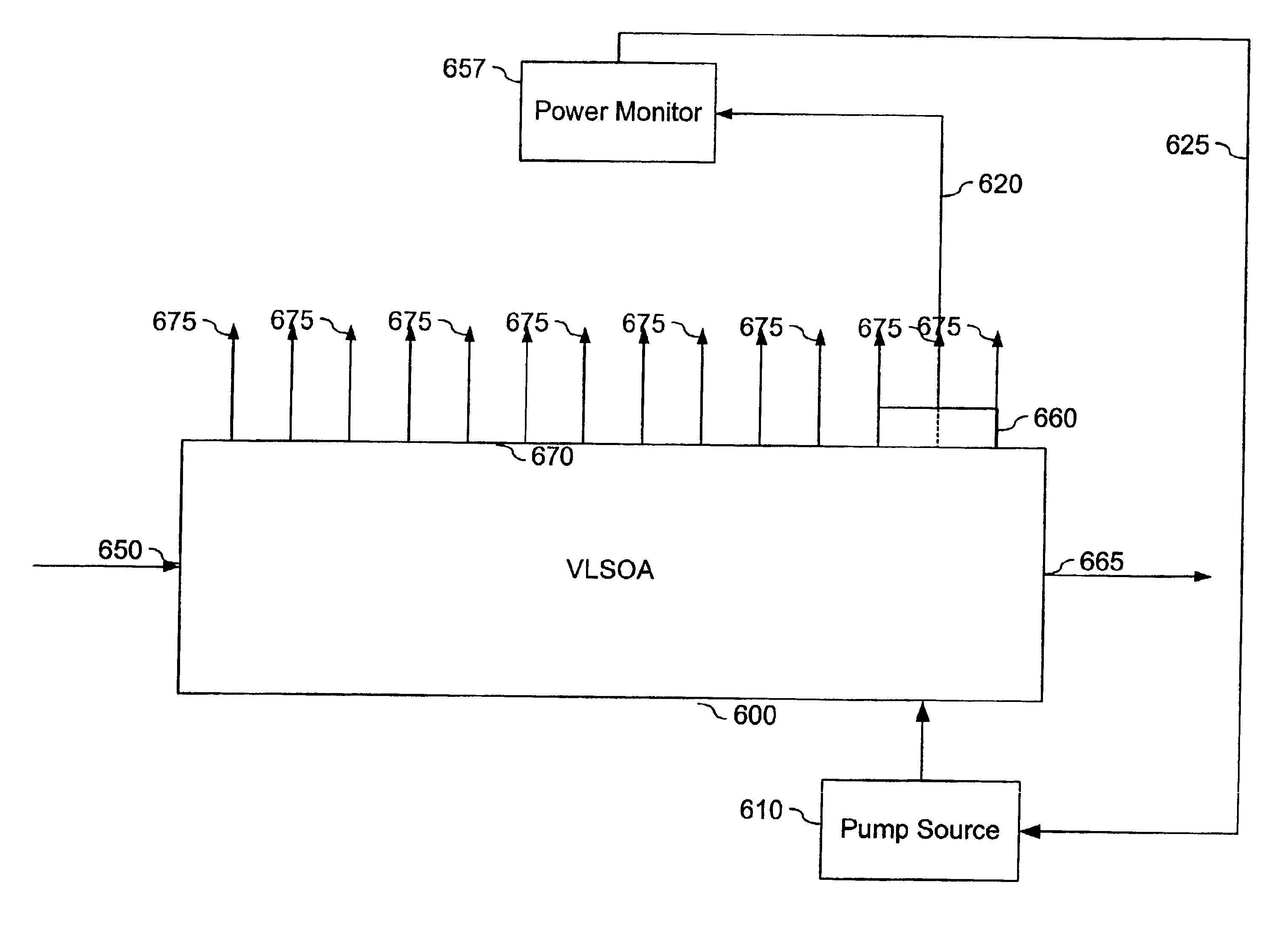
A second embodiment operates to bring a VLSOA 600 out of saturation. In this embodiment, the power monitor 657 determines if the electrical signal level on line 620 is approximately zero. A very small or non-existent electrical signal indicates that the VLSOA 600 is saturated. In response, the pump source 610 increases the electrical pump current which increases the VLSOA 600 saturation level and corresponding output power.

Thus, the present invention dynamically adjusts the electrical pump current according to the amplification of the optical signal. Additionally, the present invention provides network designers and managers an efficient way to adjust optical amplifiers as networks are scaled.

C. Saturation Protection for VLSOA

The following embodiment is a feed-forward architecture. Feedback architectures are equally possible. FIG. 7 illustrates another embodiment of VLSOA output power monitor and control according to the present invention. A first VLSOA 705 has an input 710 and ampl...


PUM


Abstract

An optical signal power monitoring and control system is described. The system comprises at least one lasing SOA that receives, amplifies, and outputs the optical signal. During the signal amplification, a ballast laser signal is output through a substrate of the lasing SOA. This ballast laser signal is indicative of the output power of the lasing SOA. At least one detector converts the ballast laser signal to an electrical signal and transmits this electrical signal to a power monitor circuit. Using the electrical signal, the power monitor determines the output power of the lasing SOA. A pump control adjusts the rate at which the lasing SOA is pumped in order to change the saturation level of the lasing SOA and its corresponding power output ceiling. According to one embodiment, the power monitor identifies when the lasing SOA is approaching saturation or is saturated. If the lasing SOA is saturated or approaching saturation, the pump control increases its pumping rate causing the saturation level of the lasing SOA to rise. As a result, the lasing SOA is provided protection from saturation.

Description

A. Technical FieldThe present invention relates generally to power control within an optical network, and more particularly, to power detection on a semiconductor optical amplifier, and in response, adjustment of a power saturation level on the semiconductor optical amplifier.B. Background of the InventionService providers are experiencing an ever-increasing demand for bandwidth fueled by Internet access, voice, data, and video transmissions and this demand for bandwidth will likely continue to grow. Due to this demand, network capacities are being stretched to their limit. As a result, there has been an increasing effort to lay fiber in order to expand the capacity of existing networks and build new higher capacity networks.Optical amplifiers, which boost the power of optical signals within these networks, are a basic building block for many types of optical systems. Fiber optic communications systems typically require the use of optical amplifiers in order to properly carry optica...

Claims


Application Information

Patent Timeline
IPC IPC(8): H01S5/00H01S5/183H01S5/50H01S5/14H01S5/0683H01S5/028H01S5/062
CPCH01S5/18311H01S5/0285H01S5/0622H01S5/0683H01S5/5072H01S5/2009H01S5/1032
Inventor DIJAILI, SOL P.WALKER, JEFFREY D.
Owner II VI DELAWARE INC
Why Eureka
Try Eureka