Lasing semiconductor optical amplifier with optical signal power monitor

Inactive Publication Date: 2004-11-23
II VI DELAWARE INC
View PDF21 Cites 14 Cited by
  • Summary
  • Abstract
  • Description
  • Claims
  • Application Information

AI Technical Summary

Problems solved by technology

Due to this demand, network capacities are being stretched to their limit.
These efforts to increase the size of network infrastructures are still unable to meet the growing demand of bandwidth-hungry clients.
However, the cost of these network management systems is often very high.
Also, often times the reliability of the network management systems is questionable due to its complexity.
Because an optical signal contains multiple signals having differing wavelengths, a network failure may only affect certain wavelengths within the signal.
In these systems, phenomena such as fiber losses,

Method used


Image

  • Lasing semiconductor optical amplifier with optical signal power monitor
  • Lasing semiconductor optical amplifier with optical signal power monitor
  • Lasing semiconductor optical amplifier with optical signal power monitor

Examples


Embodiment Construction

In the following description, for purposes of explanation, numerous specific details are set forth in order to provide a thorough understanding of the invention. It will be apparent, however, to one skilled in the art that the invention can be practiced without these specific details. In other instances, structures and devices are shown in block diagram form in order to avoid obscuring the invention.

Reference in the specification to "one embodiment" or "an embodiment" means that a particular feature, structure, or characteristic described in connection with the embodiment is included in at least one embodiment of the invention. The appearances of the phrase "in one embodiment" in various places in the specification are not necessarily all referring to the same embodiment.

A. Conventional Optical Amplifiers

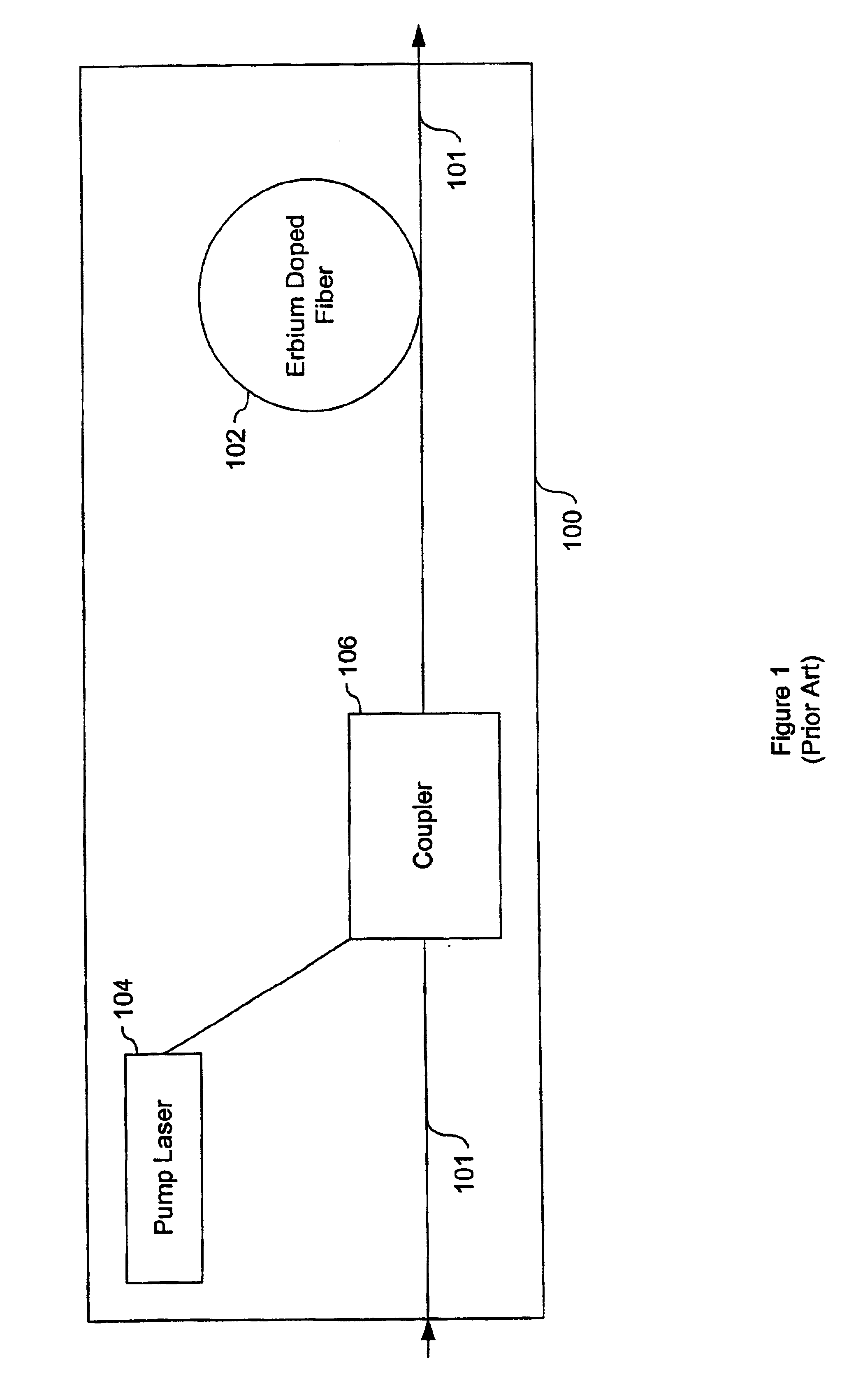
FIG. 1 is a block diagram of an erbium doped fiber amplifier (EDFA) 100. The EDFA 100 typically includes about 20 meters of erbium-doped fiber 102 inserted into the fiber optics. A ...


PUM


Abstract

An optical signal power monitoring and control system is described. The system comprises at least one lasing SOA that receives, amplifies, and outputs the optical signal. In response to the signal amplification, a ballast laser signal is output through a substrate of the lasing SOA. This ballast laser signal is indicative of the optical signal power. At least one detector converts the ballast laser signal to an electrical signal and transmits this electrical signal to a power monitor circuit. Using the electrical signal, the power monitor signal may determine the power of the electrical signal and the gain across the lasing SOA. A gain control circuit may adjust the gain across a tunable-gain lasing SOA or multi-stage optical amplifier in order to optimize the optical signal's strength. The electrical signal power and lasing SOA gain may be transmitted to a terminal to display this information or a warning may be generated when certain criteria are met.

Description

1. Field of InventionThe present invention relates generally to power monitoring of lasing semiconductor optical amplifiers (SOA). Particularly, the present invention relates to monitoring emitted lasers through a cavity surface of the lasing SOA in order to determine a gain corresponding to the lasing SOA. More particularly, the present invention relates to monitoring optical signal power and adjusting gain across the lasing SOA in order to optimize the optical signal power.2. Description of Related ArtService providers are experiencing an ever-increasing demand for bandwidth fueled by Internet access, voice, data, and video transmissions and this demand will continue to grow. Due to this demand, network capacities are being stretched to their limit. As a result, there has been an increasing effort to lay fiber to build out the backbone of existing networks.These efforts to increase the size of network infrastructures are still unable to meet the growing demand of bandwidth-hungry ...

Claims


Application Information

Patent Timeline
IPC IPC(8): H01S5/00H01S5/183H01S5/50H01S5/0683H01S5/14H01S5/028H01S5/062
CPCH01S5/18311H01S5/2027H01S5/0285H01S5/0622H01S5/0683H01S5/1032H01S5/5072H01S5/2009H01S5/5063H01S5/141
Inventor DIJAILI, SOL P.WALKER, JEFFREY D.
Owner II VI DELAWARE INC
Why Eureka
Try Eureka