
Oscillator providing waveform having dynamically continuously variable waveshape

a technology of oscillator and waveform, which is applied in the direction of instruments, electrotrophic musical instruments, etc., can solve the problems of consuming substantial memory, limiting the capabilities otherwise provided by sawtooth wave generation, and high filtering cos

Inactive Publication Date: 2004-10-19
YOUNG CHANG AKKI
View PDF11 Cites 4 Cited by
  • Summary
  • Abstract
  • Description
  • Claims
  • Application Information

AI Technical Summary

Benefits of technology

In addition to providing rich, continuous waveshapes, the oscillator of the present invention is dynamically variable under control of the user. Thus, during performance, the user not only can select among a wide variety of waveshapes, but can quickly vary the selection, and can further transition smoothly among them.

Problems solved by technology

However, because of this content, they pose significant problems with respect to the creation of undesired alias images, and significant filtering is often required to prevent this aliasing.
Filtering is expensive in digital circuitry in terms of both processing power and processing time required for effective filtering, and this restricts the capabilities otherwise provided by sawtooth wave generation.
While extremely useful, wavetables consume substantial memory.
Although this is less of a problem now than formerly in light of the decreasing costs of memory, it still places basic limitations on the number of independent waveshapes that can practically be stored in memory on a given synthesizer.
Despite significant increases in computing power with time, there is always more that is sought to be done in music synthesis than there is time to do it from a computational viewpoint, and thus oscillator efficiency may determinative of its usability in a particular instrument.
However, such additional processing consumes additional time and system resources, and it is highly desirable to avoid it when possible, rather than attempt to compensate for it subsequently.
Further, signals such as alias signals which are within the frequency band of interest cannot be removed without also removing signal desired components.

Method used


Image

  • Oscillator providing waveform having dynamically continuously variable waveshape
  • Oscillator providing waveform having dynamically continuously variable waveshape
  • Oscillator providing waveform having dynamically continuously variable waveshape

Examples


Embodiment Construction

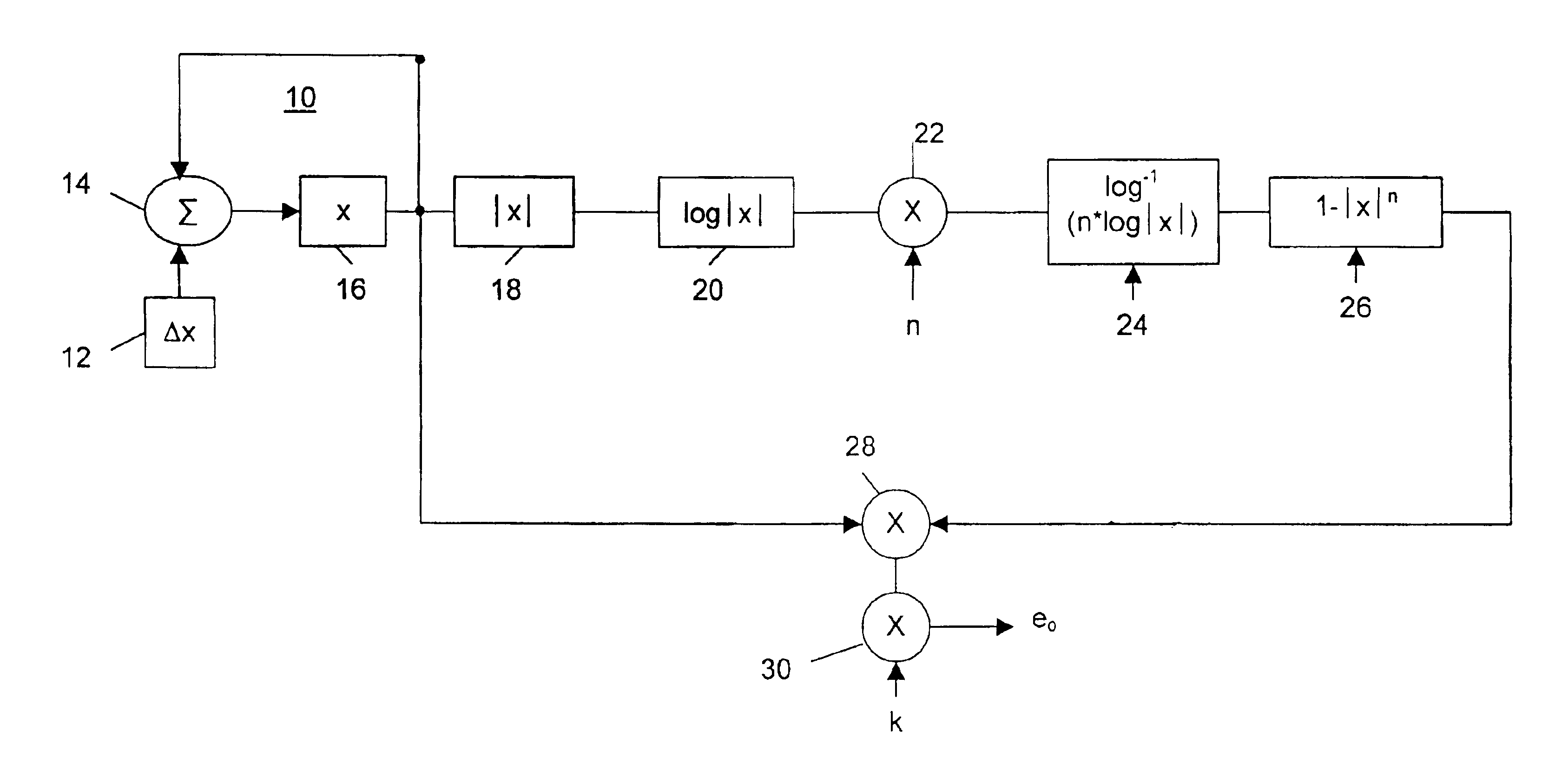
In FIG. 1, an oscillator 10 in accordance with the invention includes a register 12 for receiving a phase increment .DELTA.x of a phase x, -1<=x<=1. The increment .DELTA.x is the fractional increment in phase per cycle of waveform, and defines the frequency f of the wave to be generated. Preferably, this increment is input by the user, for example, by means of control knobs, sliders, etc. on a musical synthesizer unit.

The register 12 also provides to a summer 14 an input from the previous value of a phase accumulator register 16. The summer adds the respective inputs (x and .DELTA.x) that are applied to it and provides an output to register 16 which holds the current phase x. The elements 12, 14 and 16 thus form a basic linear accumulator which generates a stepped ramp signal, x.sub.n+1 =x.sub.n +.DELTA.x whose repetition rate (frequency) is given by f=SR / .DELTA.x, where SR ("the sampling rate") is the rate at which the phase increments .DELTA.x are applied to the summer; this type ...


PUM


Abstract

An oscillator for digital music synthesis that provides a smooth waveform that is rich in harmonic content and whose shape is continuously and dynamically variable over a wide range of harmonically rich shapes. The oscillator is efficient in that it generates the shapes in a time consonant with sampling rates commonly used in music synthesis, and is generally free of discontinuities which would otherwise create audible alias components on subsequent signal processing.

Description

1. Field of the InventionThe inventions relates to oscillators for use in music synthesizers, and comprises an oscillator providing a smooth waveform rich in harmonic content whose shape is continuously and dynamically variable over a wide range of harmonically rich shapes.2. Background InformationOscillators play a central role in music synthesis. In general, they provide a basic waveshape, or components or prototypes of a desired waveshape, which are then further processed to achieve the desired shape. For example, in additive (Fourier) synthesis, oscillators are commonly used to generate the constituents of a wave which, when added together, produce the desired waveshape. In subtractive synthesis, oscillators provide a prototype or basic wave which is then further processed, e.g., by filtering and the like to remove some constituents and enhance others, to thereby form the desired waveshape.Sawtooth waveforms provide a rich source of signals for creation of electronic music by me...

Claims


Application Information

Patent Timeline
Patent Type & Authority Patents(United States)
IPC IPC(8): G10H5/00G10H1/06G10H5/12G10H7/10G10H7/08G10H1/08
CPCG10H1/08G10H5/12G10H7/10G10H2250/545G10H2250/471
Inventor CHIDLAW, ROBERTMUHA, RALPH
Owner YOUNG CHANG AKKI
Learn More