

Hollow surface illuminator
a technology of light-conducting units and hollow surfaces, which is applied in the direction of reflex reflectors, lighting and heating apparatus, instruments, etc., can solve the problems of large amount of light leakage near, difficult to produce the above-described conventional light-conducting units having a relatively small thickness, and complicated unit structure. achieve the effect of reducing the weight of the uni
- Summary
- Abstract
- Description
- Claims
- Application Information
AI Technical Summary
Benefits of technology
Problems solved by technology
Method used
Image

Examples
first embodiment
In the present invention, of the two prismatic films, the first prismatic film, which is placed on the light-emitting surface side, is placed so that its prismatic surface faces outside of the light-conducting space. In this case, the direction of the prisms of the first prismatic film should not be parallel with the direction of the light. Thereby, the light-leaking effect and the light-propagation effect are well balanced, and thus the thickness of the light-conducting unit can be easily reduced.
In this embodiment, the three-dimensional arrangement and the shape of the prisms of the second prismatic film are not limited. However, the direction of the prisms of the second prismatic film is preferably not parallel with the direction of the prisms of the first prismatic film, in particular, the angle between the two directions of the prisms is preferably in the range between 40 and 90 degrees. Thus, the light-leaking effect and the light-propagation effect are very easily balanced, e...
second embodiment
In the present invention, the prismatic surface of the first prismatic film is placed with facing outside of the light-conducting space and the direction of the prisms of the first prismatic film is in parallel with the direction of the light. In this embodiment, the three-dimensional configuration of the second prismatic film is defined as follows. That is, the direction of the prism of the second prismatic film is not parallel with the direction of said light. Thereby, the light-leaking effect and the light-propagation effect are well balanced, and thus the thickness of the light-conducting unit can be easily reduced. The angle between the direction of the prisms of the second prismatic film and the direction of the light is not 0 (zero), that is, these two directions are not parallel with each other. In general, such an angle is in the range between 40 and 90 degrees.
third embodiment
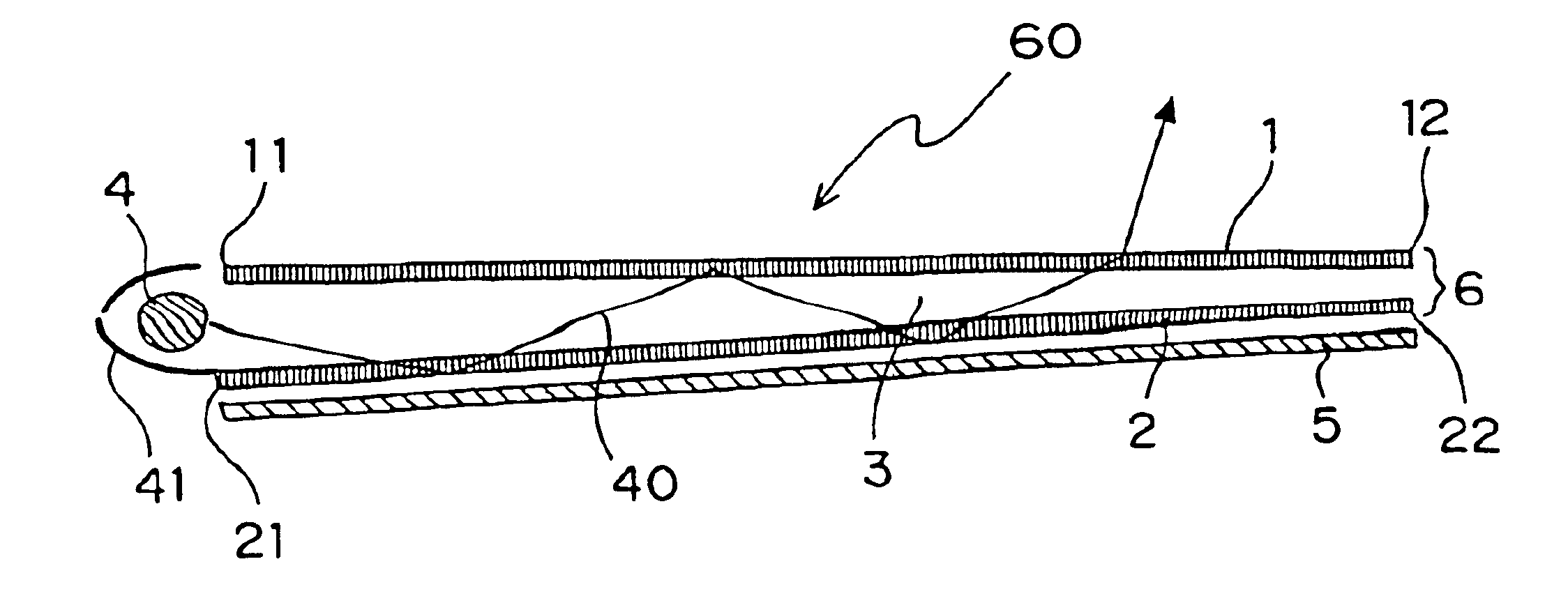
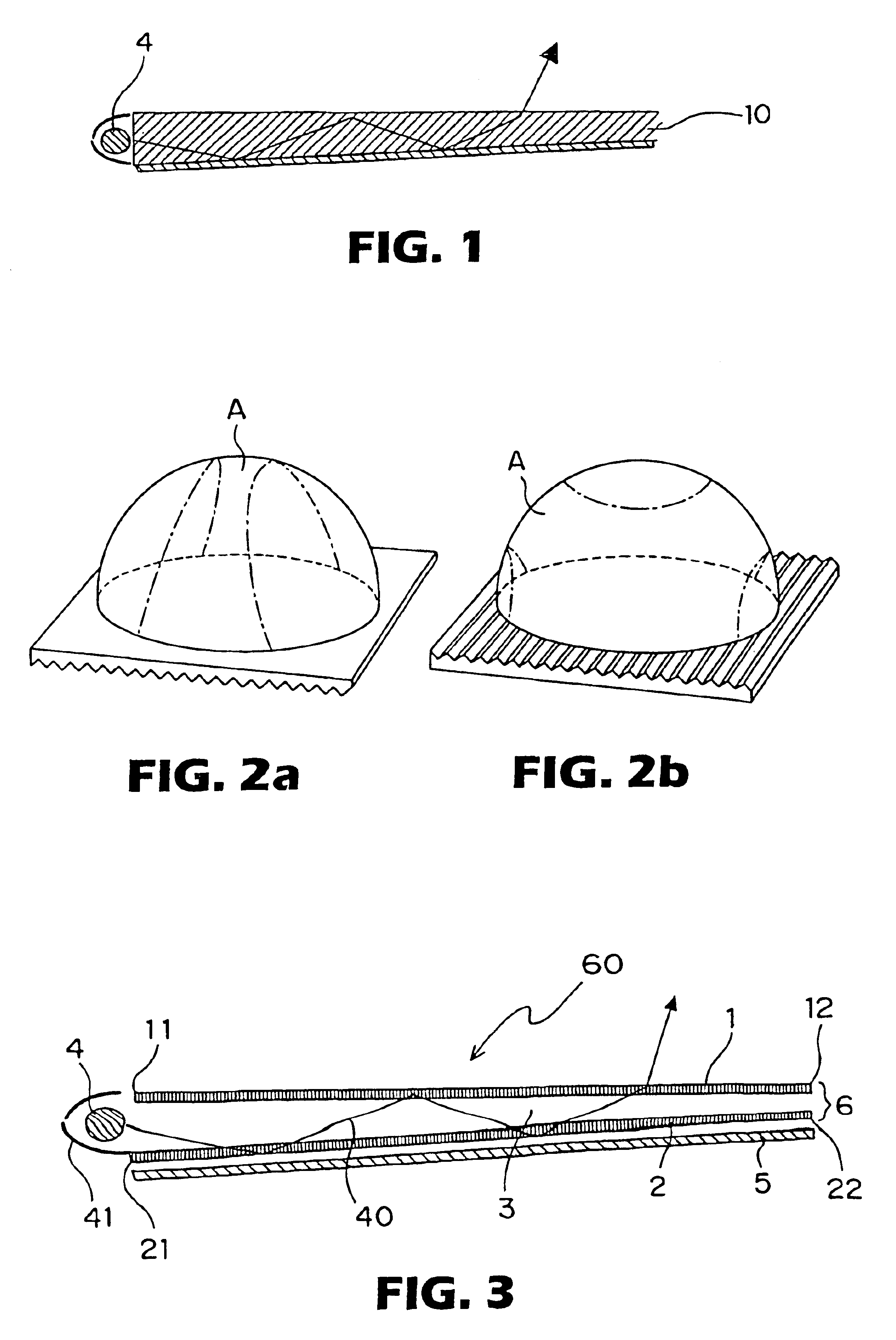
In the present invention, the prismatic surface of the first prismatic film is placed with facing outside of the light-conducting space, the direction of the prisms of the first prismatic film is parallel with the direction of the light, and also the direction of the prism of the second prismatic film is parallel with the direction of the light. In this embodiment, the relative configuration of the two prismatic films is defined as follows. That is, as shown in FIG. 3, the two prismatic films are arranged so that the height (the size in the thickness direction) of the light-conducting space decreases from the opening at the first edges of the films towards the farthest edges from the opening. The prismatic surface of the second prismatic film is placed facing outside the light-conducting space. Thereby, the light-leaking effect and the light-propagation effect are well balanced, and thus the thickness of the light-conducting unit can be easily reduced.
In general, the structure, in w...
PUM
 Abstract
Description
Claims
Application Information