
Isochronous packet transfer method, computer readable recording media recorded with control program for executing isochronous packet transfer, and bridge and packet transfer control LSI

a technology of isochronous packet transfer and computer readable recording media, which is applied in the direction of data switching networks, instruments, frequency-division multiplexes, etc., can solve the problems of insufficient time of sub-action gaps at the end of the isochronous period, inconvenient operation of the control program, and inability to transmit cycle start packets

Inactive Publication Date: 2004-11-02
MALIKIE INNOVATIONS LTD
View PDF12 Cites 38 Cited by
  • Summary
  • Abstract
  • Description
  • Claims
  • Application Information

AI Technical Summary

Problems solved by technology

On the other hand, in the situation such as the case where the packet being transferred is on the bus, the cycle start packet cannot be transmitted until after transmission of this packet has been completed.
Therefore, the time of the sub-action gap at the end of the isochronous period cannot be sufficiently maintained.
In the above manner, when a cycle delay is not given by the bridge, the problem arises in that there is a contravention of the upper limit of the isochronous period, and a cycle where an isochronous packet is missed appears.
In this way, if consideration is also given to jitter in the cycle frequency in addition to arbitration or gap, it is insufficient if the bridge only gives a delay of one cycle.
This value of 20 kilobytes is an extremely large value when considering the current fabrication technology for link layer LSI's, and the resultant cost increase due to the increase in chip size cannot be avoided.
In spite of this, even if the size of the transmit buffer is reduced in order to keep down cost, since the buffer which can be used per one cycle is reduced, there is a problem in that this imposes a limit on the transfer throughput of the bridge.
Furthermore, when the conventional transmit buffer control is used, a problem such as shown in FIG. 24 also occurs.
Therefore, there is the problem of the occurrence of jitter in the output portal side bus.
Furthermore, even under conditions where a transmit delay of the cycle start packet exists, a constant transfer delay is given to the isochronous packet.
Furthermore, in the case where the isochronous packet is transferred passing through several bridges, the delays for each passing of the bridge accumulate.
In particular, with a construction with the bridges connected in multistage, since the delay accumulates each time a bridge is passed, the effect due to reducing the delay amount for each bridge is significant.
Due to the influence of such a delay, the delay information 165 can be erroneous.
As a result, there is not longer the possibility of the reference cycle identification information being produced in the time band where a phase offset occurs between the buses when the input side bus and the output side bus are inter-bus synchronized.

Method used


Image

  • Isochronous packet transfer method, computer readable recording media recorded with control program for executing isochronous packet transfer, and bridge and packet transfer control LSI
  • Isochronous packet transfer method, computer readable recording media recorded with control program for executing isochronous packet transfer, and bridge and packet transfer control LSI
  • Isochronous packet transfer method, computer readable recording media recorded with control program for executing isochronous packet transfer, and bridge and packet transfer control LSI

Examples


Embodiment Construction

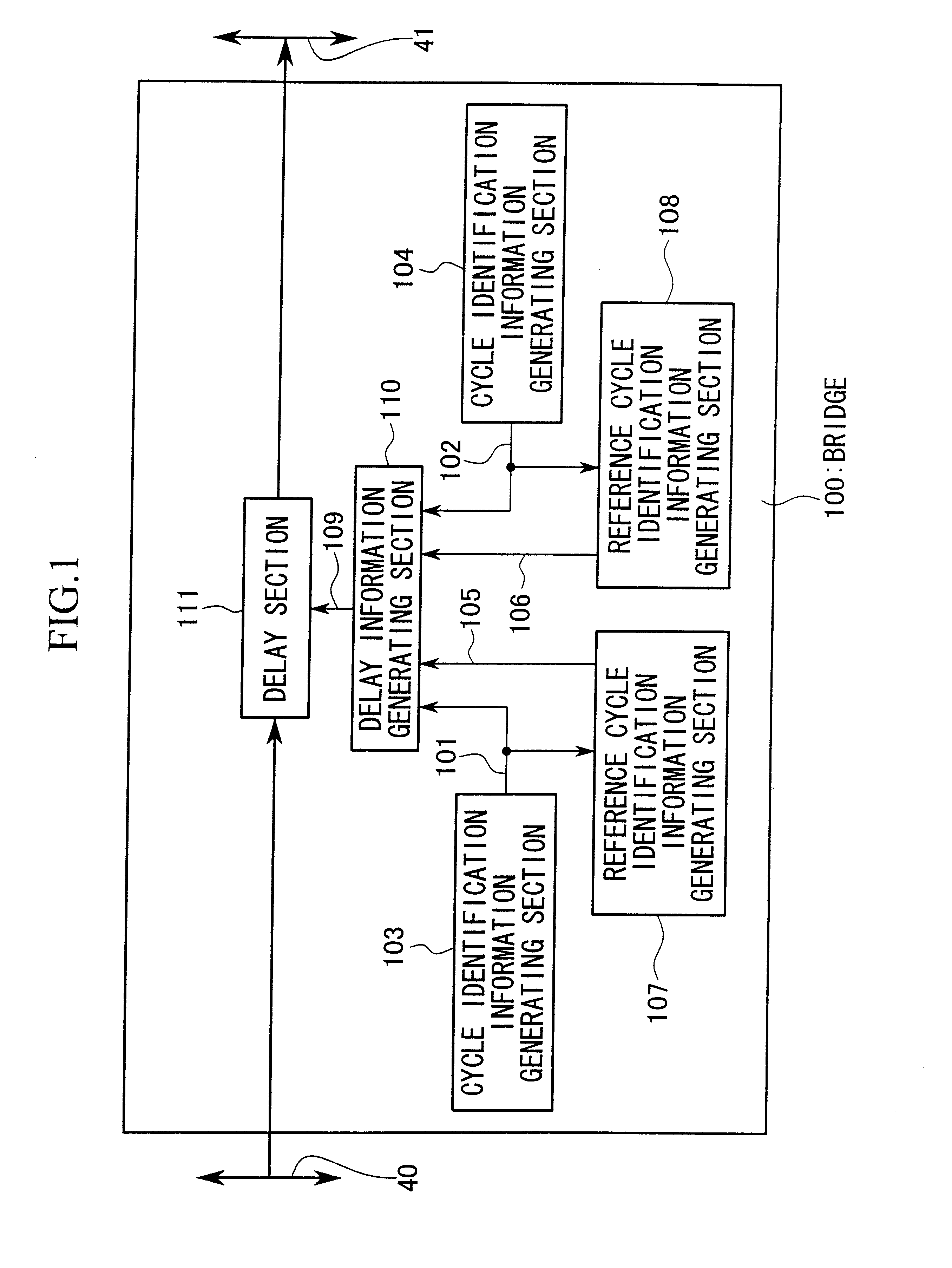
The above mentioned various embodiments are all related to bridges having three portals. However, the number of portals provided for each bridge may be any number provided this is "2" or more. In particular, with a bridge incorporating two portals, this may comprise a switching fabric which fixedly connects an input port and an output port connected to mutually different portals. Therefore, the construction of the bridge can be a very simply construction. Moreover in this case, concerning the plurality of link layer LSI's or the link function section, the construction may be such that the interface to and from the switching fabric is a direct connection, with the switching fabric omitted.

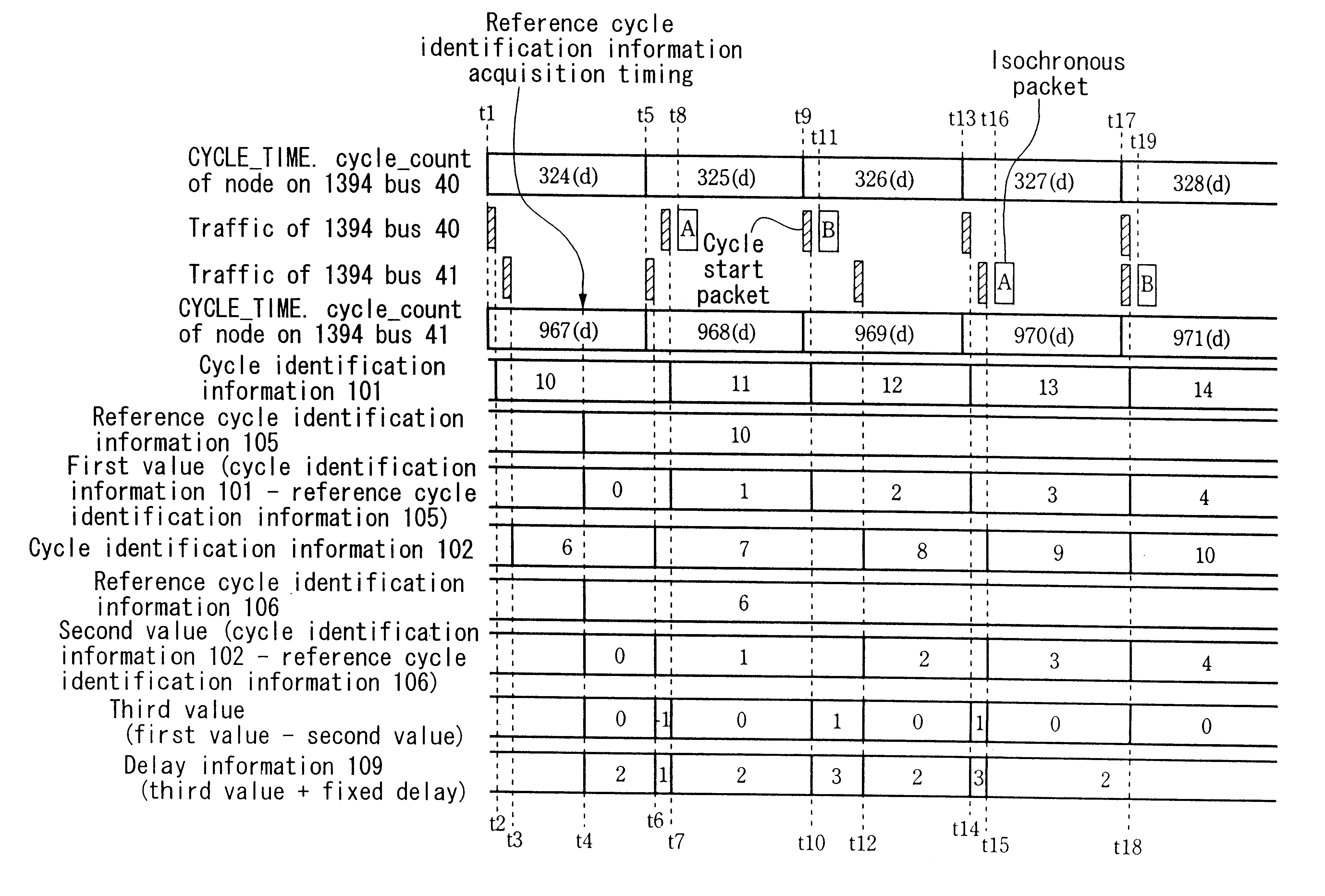
Furthermore, with the above-mentioned embodiments, in obtaining the delay amount, the "2" corresponding to the fixed delay amount is added to the third value. However this fixed value "2" may be included in the first value or the second value.

Moreover, in the above-mentioned description, the already...


PUM


Abstract

An isochronous packet transfer method is provided which can reduce a transmit buffer size required for isochronous packet transfer, and which can give a constant delay to an isochronous packet even if transmission of a cycle start packet is delayed. An isochronous packet received from an input side bus is input to a delay section, and this isochronous packet is delayed in accordance with delay information and is transmitted to an output side bus. Input side and output side cycle identification information generating sections respectively output cycle identification information which changes at a timing at which a cycle start packet is sent to the input side bus and the output side bus. Input side and output side reference cycle identification information generating sections sample the input side and output side cycle identification information at predetermined timing and output input side and output side reference cycle identification information. A delay information generating section adds a fixed delay to a difference in the elapsed cycle number for each bus from the predetermined timing, based on input side and output side cycle identification information and input side and output side reference cycle identification information to generate delay information.

Description

1. Field of the InventionThe present invention relates to an isochronous packet transfer method for transferring a packet for which the transfer band has been previously secured, on a communications network which uses a bus conforming to the specifications of IEEE (Institute of Electrical and Electronic Engineers) standard 1394 or USB (Universal Serial Bus). Furthermore, the present invention relates to a recording medium on which is stored an isochronous packet transfer control program serving as a means for executing the isochronous packet transfer method, a bridge, and a packet transfer control LSI (Large Scale Integrated Circuit).This application is based on Japanese Patent Application No. Hei 11-271388, the contents of which are incorporated herein by reference.2. Description of the Related ArtRecently, as a high performance serial bus standard having high speed transmission capability of for example 100 megabit per second (S100), 200 megabit per second (S200), or 400 megabit p...

Claims


Application Information

Patent Timeline
IPC IPC(8): H04L12/64H04L7/02H04L29/02H04L12/40H04L12/46H04L29/08
CPCH04L12/40058H04L12/40065H04L12/6418H04L12/40091H04L2012/6456H04L2012/6435
Inventor DOMON, WATARU
Owner MALIKIE INNOVATIONS LTD
Learn More