

Transfer case with synchronizer clutch
a technology of synchronizer and transfer case, which is applied in the direction of mechanical actuation clutch, transportation and packaging, etc., can solve the problems of excessive transfer case cost, synchronizer complexity, and allowing a full shi
- Summary
- Abstract
- Description
- Claims
- Application Information
AI Technical Summary
Benefits of technology
Problems solved by technology
Method used
Image

Examples
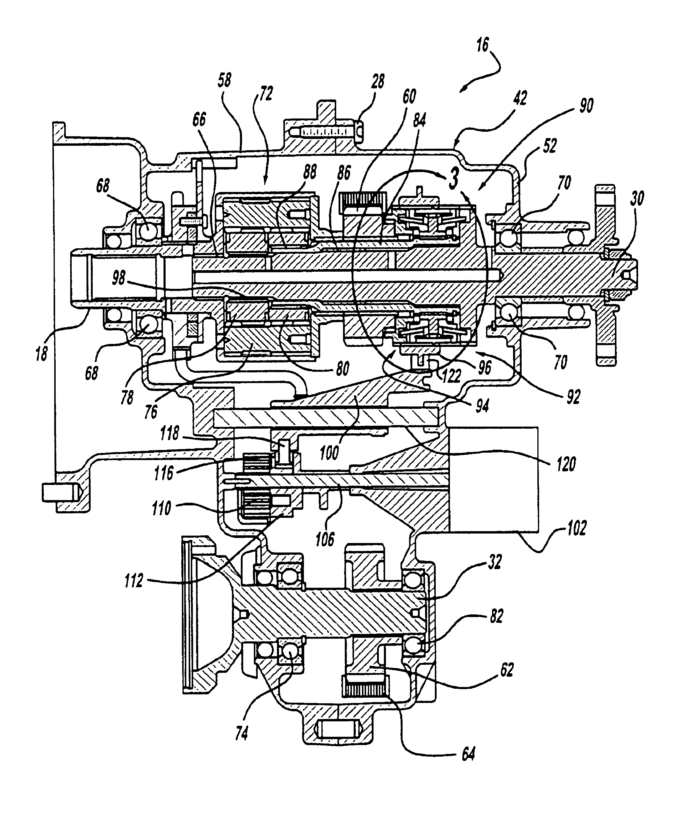
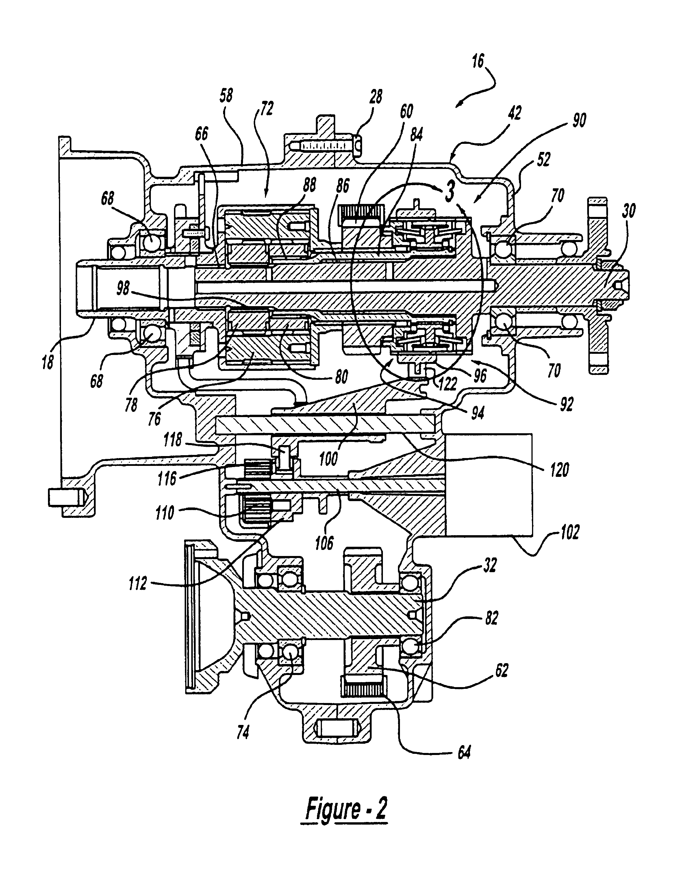
case 16
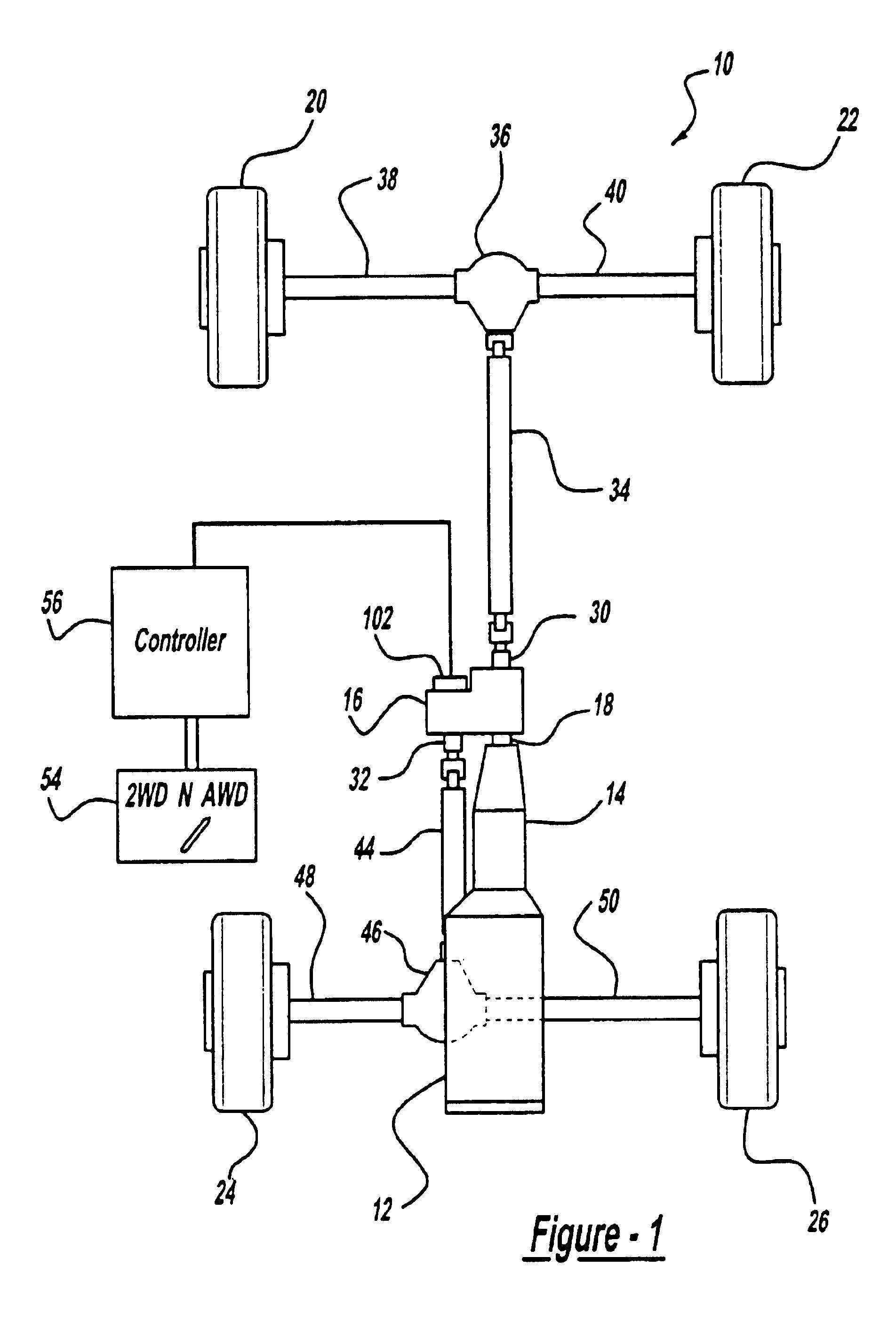
The transfer case 16 includes a rear output shaft 30 and a front output shaft 32. The rear output shaft 30 is coupled to a rear drive shaft 34, which is coupled to a rear differential 36. A first rear axle 38 is coupled at one end to the differential 36 and at an opposite end to the wheel 20. Likewise, a second rear axle 40 is coupled at one end to the differential 36 and at an opposite end to the wheel 22. The transfer case 16 provides output power on the rear shaft 30, which provides rotational energy to the rear drive shaft 34. This rotational energy is transferred through the rear differential 36 and the axles 38 and 40 to the wheels 20 and 22 in a manner that is well understood in the art.
The front output shaft 32 is coupled to a front drive shaft 44, which is coupled to a front differential 46. A first front axle 48 is coupled at one end to the front differential 46 and at an opposite end to the wheel 24. Likewise, a second front axle 50 is coupled at one end to the front diff...
PUM
 Abstract
Description
Claims
Application Information