Gas compressor and method with improved valve assemblies

Inactive Publication Date: 2004-11-16
DRESSER RAND CO
View PDF21 Cites 38 Cited by
  • Summary
  • Abstract
  • Description
  • Claims
  • Application Information

AI Technical Summary

Problems solved by technology

However, this flow area through the valve assembly is often limi

Method used


Image

  • Gas compressor and method with improved valve assemblies
  • Gas compressor and method with improved valve assemblies
  • Gas compressor and method with improved valve assemblies

Examples


Embodiment Construction

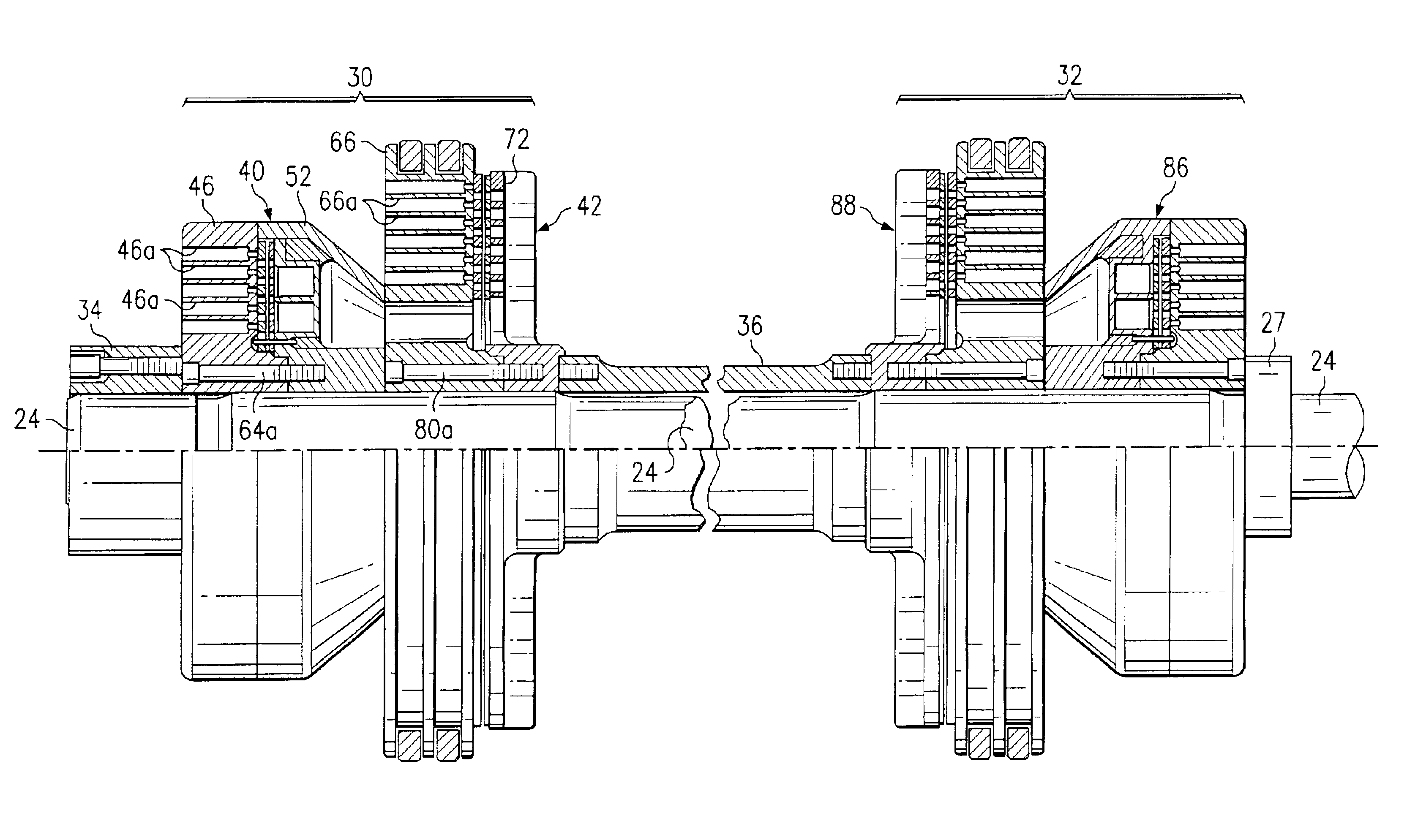
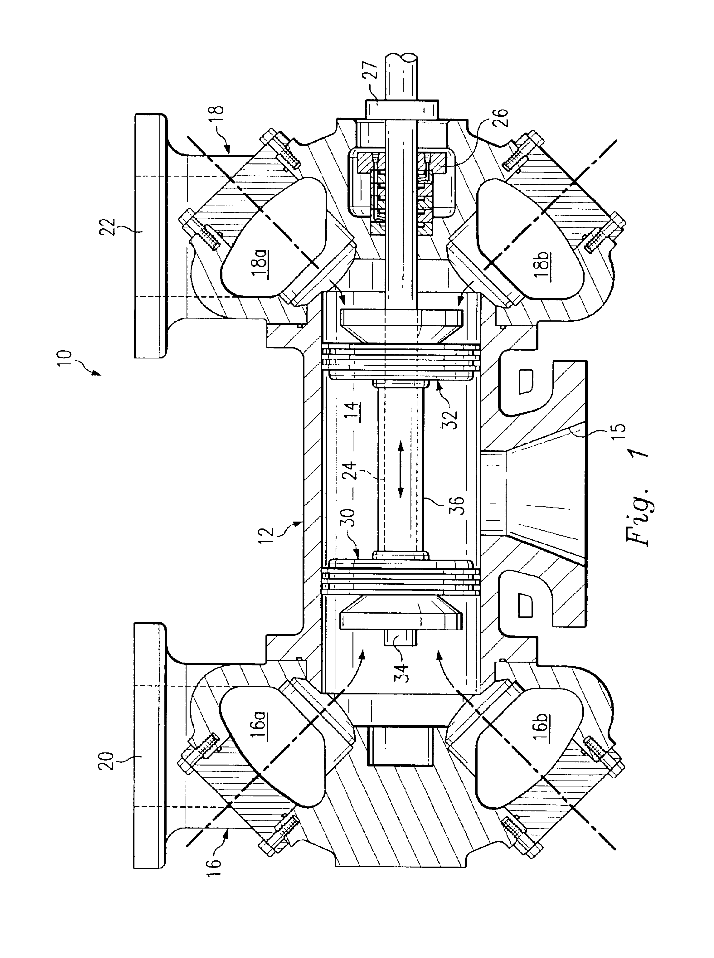
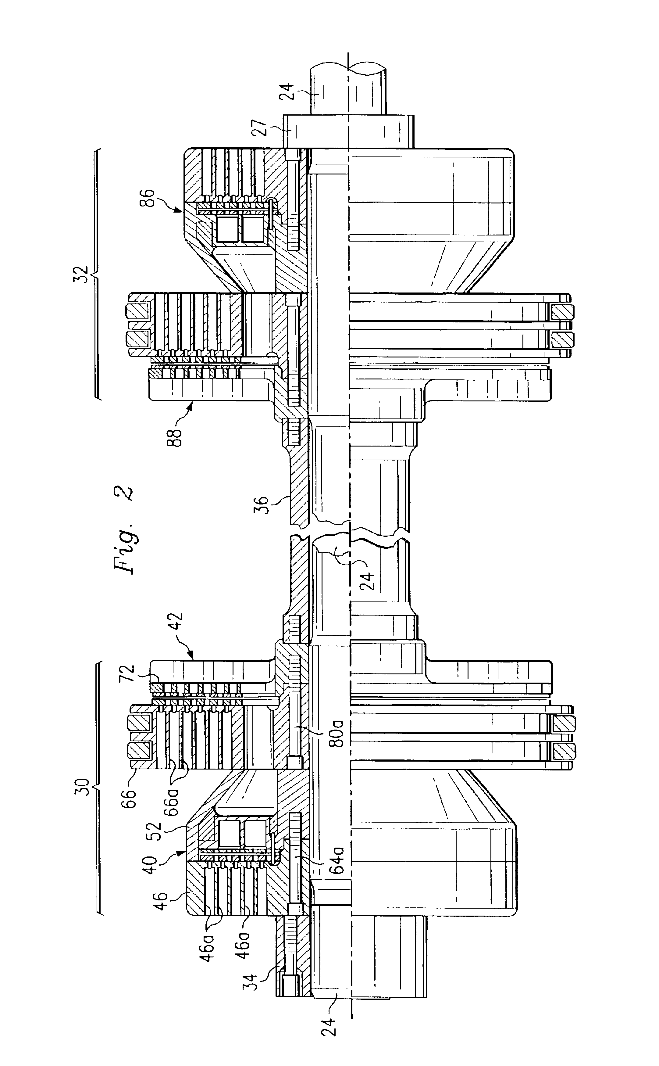
Referring to FIG. 1 of the drawings the reference numeral 10 refers, in general, to a compressor for compressing a fluid, such as gas, according to an embodiment of the present invention. The compressor 10 includes a cylindrical housing 12 defining an internal cylindrical bore 14 and a radially extending outlet 15 that registers with the bore 14.

An outer head 16 is formed at one end of the housing 12, and a frame head 18 is mounted at the other end of the housing. A plurality of inlet chambers are formed through the head 16 with two being shown in FIG. 1 and referred to by the reference numerals 16a and 16b. The inlet chambers 16a and 16b, as well as the other inlet chambers in the head 16, are interconnected and are in fluid communication with an inlet conduit 20 formed on the body member 12.

The head 18 is identical to the head 16 and, as such, has a plurality of inlet chambers formed therein, two of which are shown in FIG. 1 and referred to by the reference numerals 18a and 18b. T...


PUM


Abstract

A gas compressor and method according to which a piston assembly reciprocates in a bore to draw the fluid to be compressed into the bore during movement of the piston unit in one direction and to compress the fluid during movement of the piston unit in the other direction.

Description

BACKGROUNDThis invention relates, in general, to a fluid compressor, and, more particularly, to a compressor having improved discharge valves.Many reciprocating compressor cylinders utilize a piston assembly that reciprocates in a cylinder formed in the compressor body, with outer heads closing off the ends of the cylinder. In these arrangements, the piston assembly often includes a discharge valve that controls the gas flow through its body structure into the cylinder and then compresses the fluid before permitting the compressed fluid to discharge through the outlet.These type of valve assemblies utilize a plate valve which "lifts" off a valve seat in response to a pressure differential created from one side of the valve to the other side, to permit flow through the assembly. However, this flow area through the valve assembly is often limited in size, which compromises the efficiency of the compressor.Therefore, what is needed is a compressor of the above type according to which t...

Claims


Application Information

Patent Timeline
IPC IPC(8): F04B39/00F04B39/10
CPCF04B39/1053F04B39/0016Y10T137/7839
Inventor BENNITT, ROBERT
Owner DRESSER RAND CO
Why Eureka
Try Eureka